Machine layout and dimensions
Honda’s RC211V racing machine debuted in the 2002 season when the top class of the Road Racing World Championship changed to MotoGP. Honda’s initial goal of development was to create a machine with performance to beat its NSR500.
The NSR500 was the most powerful GP500 racer of its time, taking out world titles for seven of the eight seasons from 1994 through 2001. It was equipped with a 500cc displacement, two-stroke V4 engine with maximum output that easily surpassed 180 pferdestärke (PS) in its final specifications. Machine weight was 131 kg, which was the minimum allowed under the regulations. When the RC211V replaced the NSR500 in the top class of the championship, Honda decided to develop a 990cc displacement, four-stroke V5 engine instead. Accordingly, minimum machine weight under the regulations increased to 145 kg.
While naturally building its works road racer to the minimum regulation weight, there were unavoidable physical consequences of the RC211V being 14 kg heavier than the NSR500 that were detrimental to deceleration and steering. To develop a machine that could beat the NSR500, Honda made use of engine output that was approximately 30% more powerful to give the RC211V an advantage when accelerating out of corners. It focused particularly on creating a machine with greater freedom when taking a line in corners. To achieve this, it concentrated RC211V machine mass to a much higher degree than with the NSR500. It also developed a machine with a load (weight) distribution ratio of 50:50 between front and rear wheels when ridden.
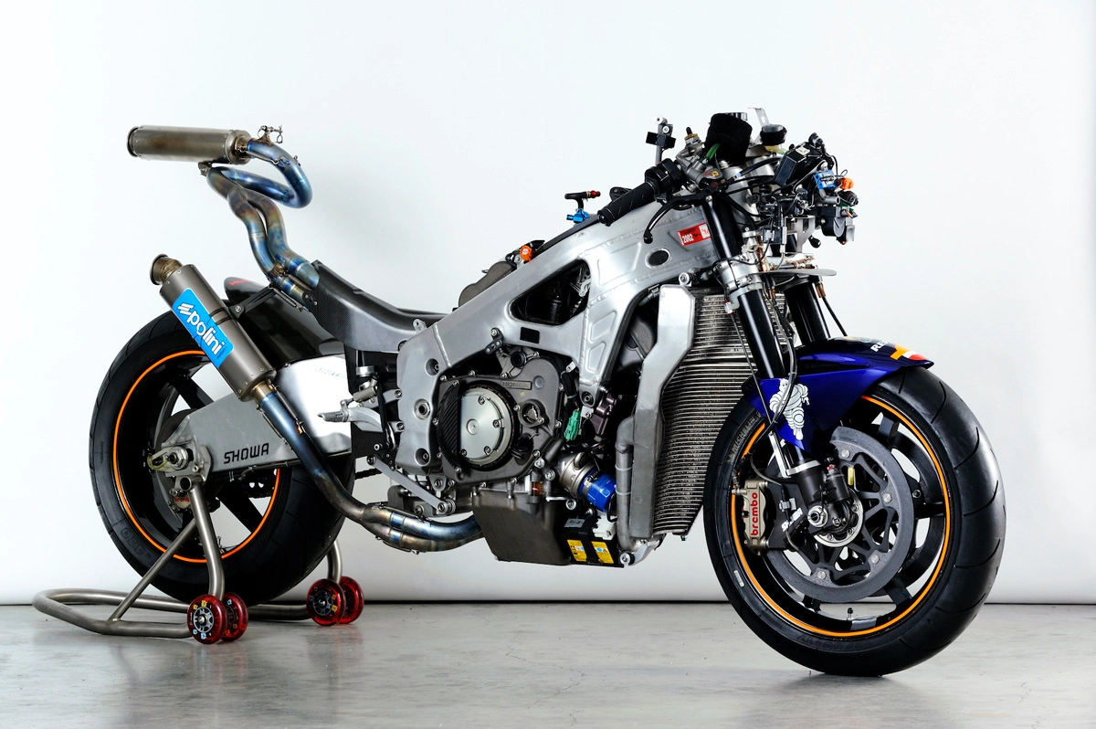
2002 NV5A machine layout
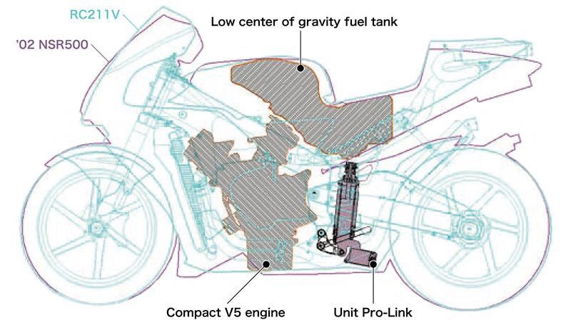
Honda’s approach to mass concentration and longitudinal weight distribution, for achieving outstanding dynamic performance, remained the same from the first-generation RC211V in 2002 (NV5A) to the last-generation RC211V in 2006 (NV5HG).
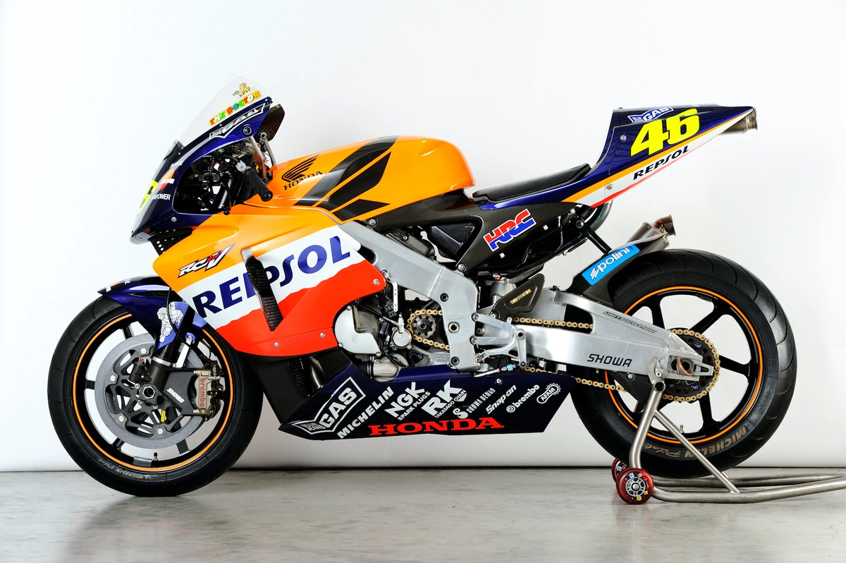
Honda works team riders in 2002 were Valentino Rossi and Tohru Ukawa, who rode the RC211V in every round of the 2002 season, the first year of the MotoGP. However, the riders had completely different physiques. As originally intended by Honda, Ukawa’s riding position on the RC211V was much further forward than on previous machines. Rossi, on the other hand, was taller so he had to sit further back on the seat, but weight distribution was set to be as close to the 50:50 ratio as possible anyway.
Honda set the standard wheelbase for its 2002 NV5A at 1,450 mm, which was 50 mm longer than its final NSR500 model. This was due to the RC211V’s center of gravity from the ground, or center of gravity height, being higher than that of the NSR500. The basic school of thought was that the angle of each apex of a triangle formed by the center of gravity and front and rear axles should be the same. All models from the NV5B in 2003 maintained the standard wheelbase of around 1,450 mm. During the period from 2002 to 2006, when maximum engine displacement was 990cc, regulations for minimum machine weights remained the same. Successive generations of the RC211V therefore remained at 145 kg and the center of gravity was largely unchanged, so there was no need to significantly change the wheelbase.
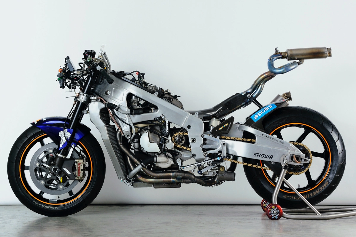
2002 NV5A
Another standard value that Honda set for successive generations of the RC211V was caster angle, which is the angle between a vertical line from the ground and the central steering axis. As a parameter with a significant impact on motorcycle handling, Honda set a caster angle of 24°. With road racers, chassis stability under braking is a critical requirement when determining caster angle. Honda found 24° to be the optimal angle for stability under repeated braking when quickly decelerating the total mass of the RC211V (machine weight of 145 kg + fuel weight + rider weight) by 200 km/h or more from the top speed of around 320 km/h. Caster angle was naturally variable, but within a range of roughly ±0.5°.
Frame and swing arm
The three moments generated around a chassis in motion are in the yaw direction (rotation around the vertical axis), pitch direction (rotation around the lateral axis), and roll direction (rotation around the longitudinal axis). The frame and swing arm (rear arm) connecting the motorcycle’s front and rear wheels require rigidity to handle the moments in each of these directions. Torsional rigidity in particular, in the roll direction, needs to be high to ensure chassis stability when starting to accelerate while leaning over in corners.
However, with a frame and swing arm built using the standard manufacturing method at the time, increasing torsional rigidity would have resulted in increased bending rigidity in the lateral direction. This excessive lateral rigidity makes it difficult to achieve good steering performance on motorcycles, so Honda chose a structure that was different from the existing NSR500 when developing its new RC211V. For many years, Honda used extruded aluminum pipe manufactured through a high-temperature, high-pressure mold extrusion process for the main members of the NSR500 chassis. For the RC211V, on the other hand, it used a method of constructing the frame and swing arm by combining aluminum sheet metal parts manufactured for each member.
2002 NV5A
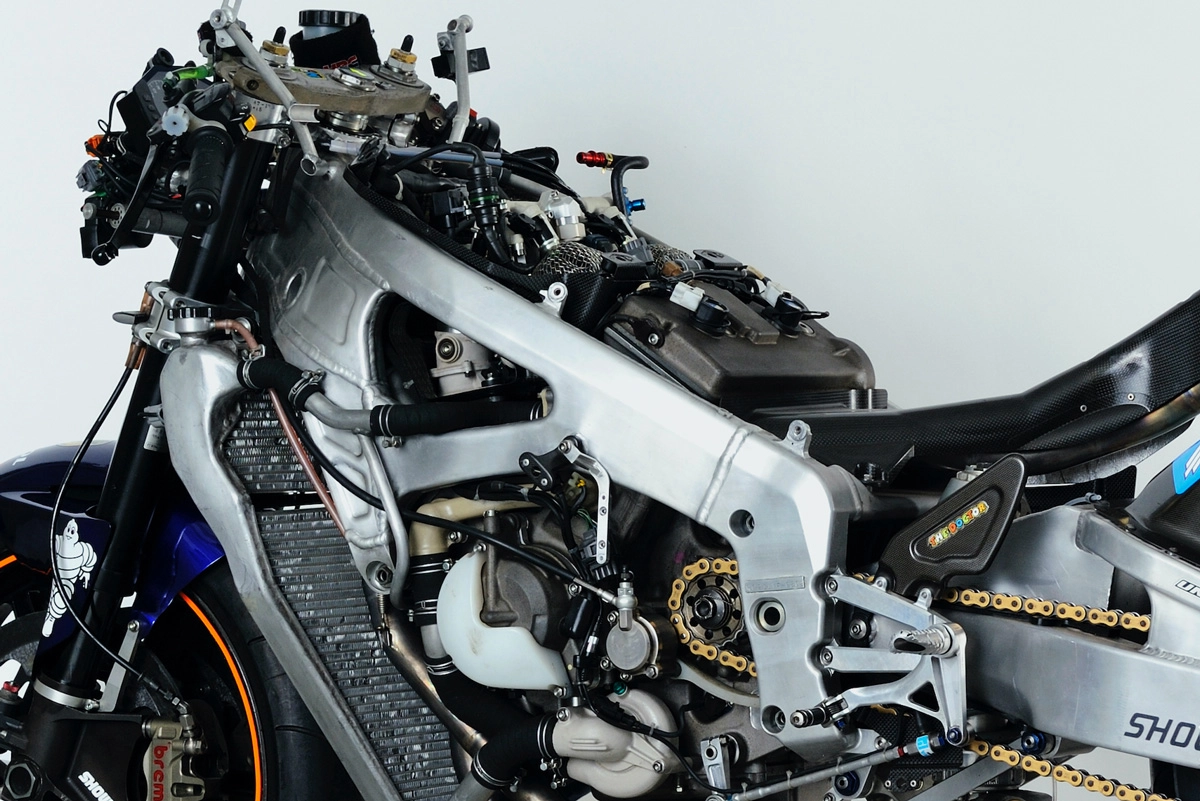
Honda used A7N01 aluminum for these members due to its high strength and age-hardenability that allowed it to return to the original strength of the base material after welding. Each member was manufactured by forming the sheet metal parts into U-shaped channels and then joining them by welding into box beams. Fully incorporating computer-aided engineering (CAE) analysis into design of the parts, Honda was able to ensure appropriate rigidity of each member by adjusting thickness of the A7N01 and the structure of the parts for each chassis member. This created a frame that appeared so slender, compared to the familiar frame of the existing NSR500, that the RC211V frame seemed much narrower and lighter overall.
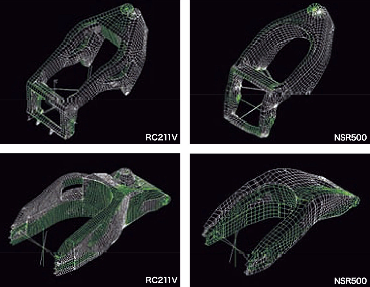
Using this manufacturing method, Honda was able to develop a frame and swing arm for its RC211V that had higher torsional rigidity and lower lateral rigidity. With the NV5A in 2002, the first RC211V, it achieved higher torsional rigidity for the frame (+23%) and swing arm (+29%), and lower lateral rigidity for the frame (-17%) and swing arm (-12%), compared to the NSR500. This gave the NV5A high chassis stability when accelerating out of corners and at other times, and a chassis that also responded favorably for the rider when leaning over in the corners.
Frame: Lateral rigidity -17% / Torsional rigidity +23%
Swing arm: Lateral rigidity -12% / Torsional rigidity +29%
When changing the rigidity settings, Honda also changed the shape of the frame compared to when the frame was manufactured using an extrusion process. Of particular importance was positioning of the forwardmost fastening point (called point “A” by Honda) where the engine was attached to the frame. To achieve a frame with lower lateral rigidity and higher torsional rigidity, Honda used CAE modeling to carefully verify the best position for this point A. As a result, it identified a forward point lower than usual that created a larger frame cross-section in the vertical direction and contributed to torsional rigidity, while its distance from the main frame pipe facilitated lateral movement (and therefore lower lateral rigidity).
With the previous NSR500, the V4 engine was mounted at three points; (1) near the crankcase rear cylinder bank flange, (2) at the top rear of the crankcase, and (3) at the bottom rear of the crankcase. Attachment point (1) was the equivalent to point A on the RC211V, and the engine hanger bracket (an inverted triangle welded to the main frame pipe) was extended and attached to this point. With the RC211V, on the other hand, the V5 engine was mounted at four points; the same (1), (2), and (3) above, plus (4) near the crankcase front cylinder bank flange. Point A on the RC211V was this attachment point (4), with the engine hanger part branching from the main frame pipe and extending further downward to position point A far from the main pipe.
2002 NV5A
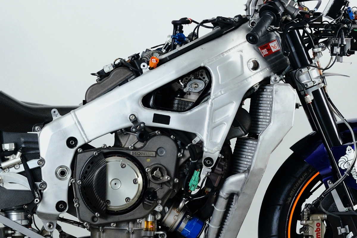
This positioning of point A was adopted for subsequent Honda road racers, and mass production sports bikes like the CBR1000RR as well. At the start of the 2002 MotoGP season, many of Honda’s competition in the MotoGP positioned their point A close to the main frame pipe, but from the 2003 season onward they had all changed point A to the same position as the RC211V.
Honda used the same frame and swing arm structure, made from sheet metal parts formed into box beams, for five of its RC211V models from the NV5A in 2002 to the NV5HD in 2006. With the final NV5HG in 2006, however, it started manufacturing many parts by machining aluminum ingots into the desired shapes. This was possible due to progress that had been made with fabrication technologies, including the mainstream use of 5-axis machining centers. With machining making it possible to make fine changes to the sheet metal thickness and other aspects depending on the part, it became easier to achieve the performance originally envisaged in the design stage.
Unit Pro-Link rear suspension
From the beginning of the 1980s, the majority of Honda motorcycles employed Pro-Link rear suspension regardless of whether they were regular street bikes or racing machines. Pro-Link is a “linkage-type” suspension system that “progressively” varies load according to suspension stroke, with the top of its cushion unit mounted to the chassis and the bottom connected to the linkage.
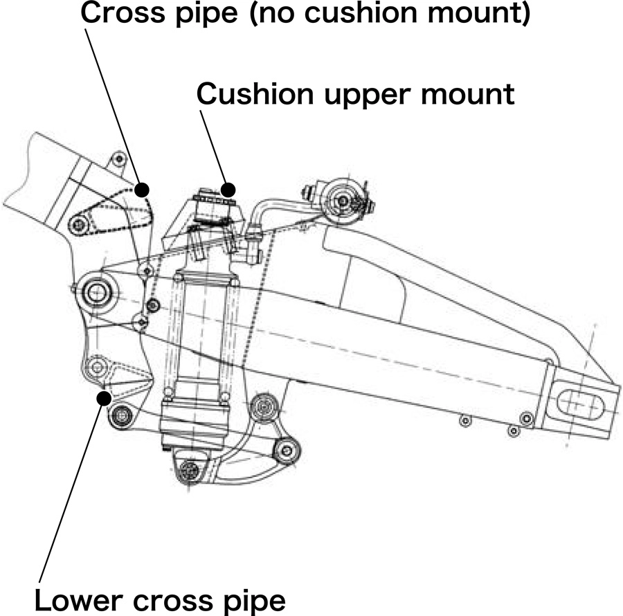
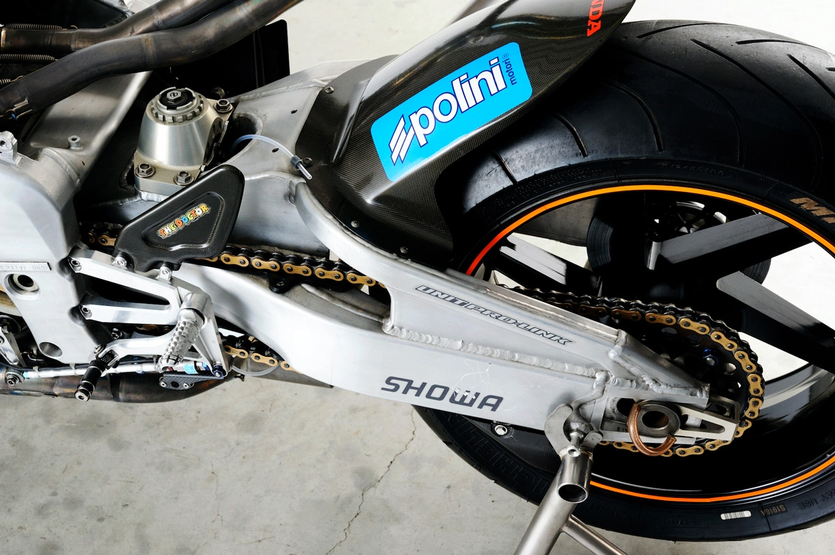
The RC211V also used a Pro-Link rear suspension system, but with specifications that were different from normal, with cushion unit upper mounts provided on the reinforcing structure located close to the swing arm base. As a rear suspension unit that worked entirely through the swing arm, Honda called this type of suspension “Unit Pro-Link.” It was used for the first time on the RC211V.
Pro-Link rear suspension
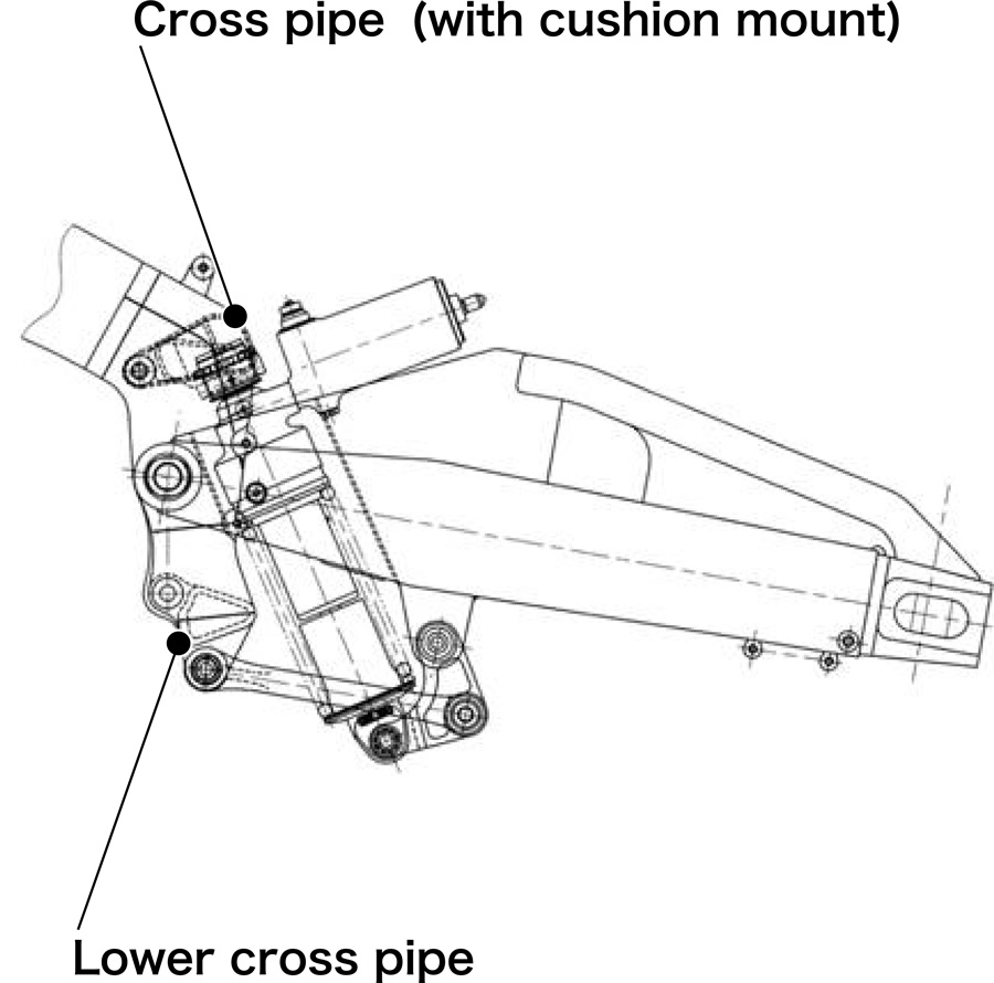
Unit Pro-Link rear suspension
2002 NV5A
The direct aim of using Unit Pro-Link on the RC211V was to eliminate the cushion unit upper mounts from the frame. This enabled Honda to implement the low center of gravity fuel tank (see below) that was one of the key means of delivering on its theme of concentration of mass. In actual use, Honda found that Unit Pro-Link also had the complementary effect of allowing the chassis to flex in the lateral direction. With standard Pro-Link rear suspension, the top of the cushion unit is mounted to the cross pipe, which is a part that connects the left and right parts of a frame. If the frame has lower lateral rigidity, it would deflect due to transfer of inputs via the cushion unit under conditions of higher rear loads, such as when exiting corners. This would then change the geometry around the main frame pipe and steering head pipe and cause the chassis to lose stability. However, this did not occur with Unit Pro-Link because it was separated from the frame, allowing the chassis to flex and achieve the desired handling performance.
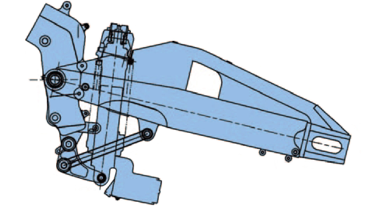
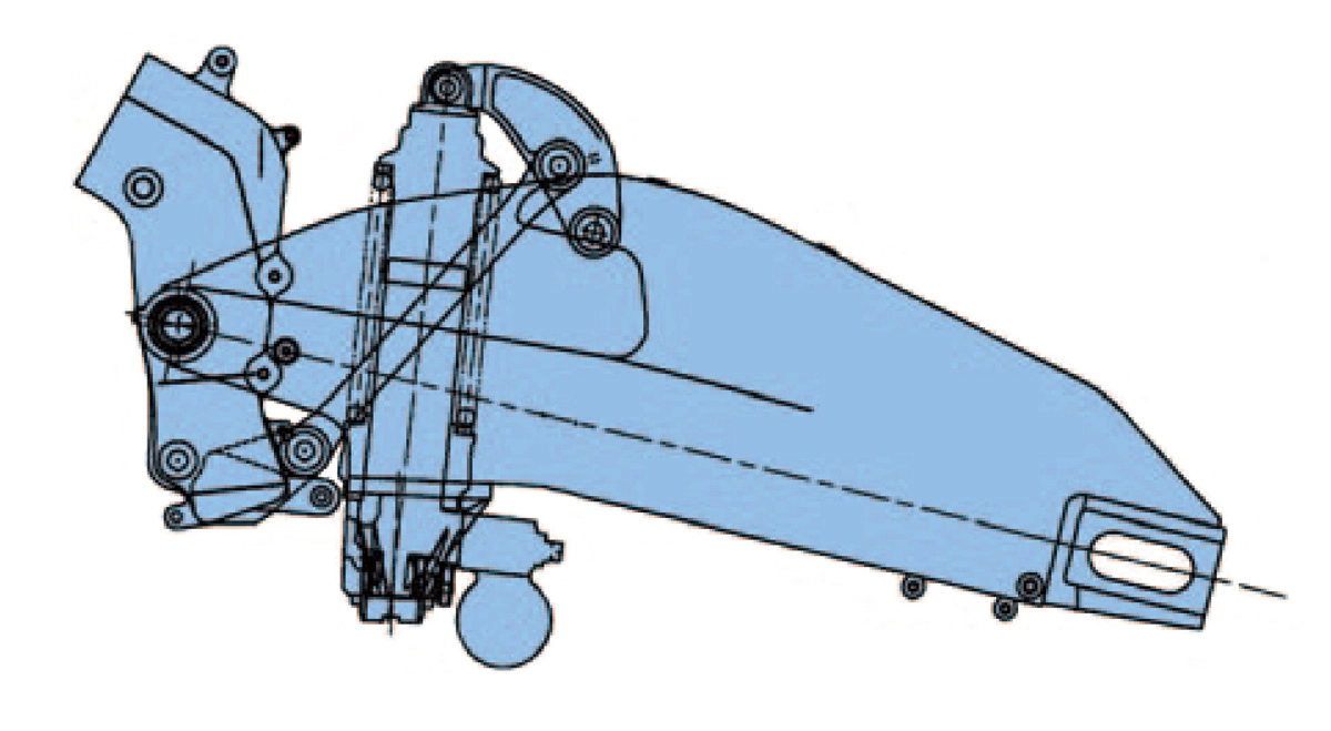
The Unit Pro-Link rear suspension system used on the NV5A in 2002, Honda’s first RC211V model, and the NV5B in 2003, was a lower-linkage type with the linkage mechanism mounted to the bottom of the cushion unit. That relationship was reversed for the NV5C in 2004 when an upper-linkage type was used. The problem with the lower-linkage type was that the direction of force on the swing arm pivot varied according to the rear suspension stroke position, which had an adverse affect on machine behavior. The upper-linkage type, on the other hand, consistently applied force to the pivot in the forward direction regardless of the rear suspension stroke position. Honda’s decision to change linkage type was based on this advantage.
Lower-linkage type Unit Pro-Link rear suspension systems
Upper-linkage type Unit Pro-Link rear suspension systems
With better chassis behavior under acceleration, the upper-linkage type also provided excellent traction. On the other hand, it was inferior in terms of rear wheel road tracking performance under deceleration. After examining this trade-off between performance parameters, Honda eventually returned to the lower-linkage type from the NV5D in 2005.
Low center of gravity fuel tank
When the MotoGP regulations were introduced in 2002, there was no maximum number of cylinders stipulated when running four-stroke machine, but engine displacement was set at a maximum of 990cc and fuel tank capacity at a maximum of 24 liters. (It was also determined in advance that fuel tank capacity would be reduced to 22 liters from 2005.)
Motorcycles generally have their fuel tanks arranged above the engine and in front of the rider. With a focus on concentration of mass for its RC211V, however, Honda used a low center of gravity fuel tank with a special shape that put around half of the 24 liters of fuel under the rider’s seat. Not only did the design lower the center of gravity for the fuel tank when full, but it also had the advantage of minimal change in center of gravity height as fuel was used.
This philosophy of a low center of gravity fuel tank was not new to Honda, having previously developed a fuel tank for mass production motorcycles equipped with in-line four-cylinder engines. The tank was installed in the same position as usual but it had a large concavity in part of its bottom surface to hold a certain amount of fuel in a low position. Adopting this philosophy on its RC211V machine and V5 engine, the fuel tank layout extended to the space below the seat as well. During testing of prototypes, Honda also manufactured a fuel tank mounted in the normal position and compared the two in actual racing. It then adopted the low center of gravity fuel tank after confirming that it produced the desired effect. As a result, it used similar fuel tank shapes through to its final RC211V model, the NV5HG in 2006.
2002 NV5A
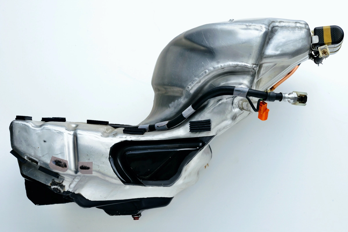
The low center of gravity fuel tank manufactured for the first-generation NV5A in 2002 was a sheet metal product made with thin aluminum sheet. The special shape resulted in very long welding lines, which made it impossible to avoid a degree of deformation. This not only made the tanks difficult to manufacture, but it had the drawback of individual tanks having different capacities, even if only slight. For this reason, Honda developed a carbon fiber reinforced plastic (CFRP) tank for the NV5B in 2003 and provided it to the Honda works’ Team HRC only. While the tank body was made of CFRP, Honda lined it with rubber to prevent fuel leaks.
The next year, in 2004, regulations required the use of a fuel tank bladder (gas bag) to hold the fuel. The CFRP tank was developed for the NV5B to stabilize tank capacity, but with fuel capacity being determined by the introduction of a bladder, Honda returned to an aluminum fuel tank from the NV5C in 2004.
Front fork
The arm supporting the front wheel on motorcycles is called the “front fork,” with the majority of motorcycles these days employing telescopic cushion units on their front fork. The cushion unit itself is also used as a structural element of the front suspension.
In this case, the front fork comprises outer and inner tubes, with the outer tubes acting as the cushion unit cases and the inner tubes, which slide within the outer tubes, including oil dampers and springs. Most road racers from the end of the 1980s have used inverted front forks with the outer tubes positioned at the top (steering head pipe side) to ensure greater rigidity around the steering head pipe.
Honda also used inverted front forks, jointly developed by itself and Showa (now Hitachi Astemo), on all of its RC211V models. The development process included Honda providing its performance requirements and Showa proposing parameters and technical specifications to meet those requirements.
2002 NV5A
From the first NV5A in 2002 to the last NV5HG in 2006, Honda continued implementing various ideas on its front forks to evolve the various parts of the system, including the damper valve. One of those changes, which had a significant effect on chassis design, was the diameter of the inner tubes. The tubes had a diameter of 47 mm for the NV5A in 2002 and the NV5B in 2003, but for the NV5C in 2004, Honda made a comparatively large change when it reduced diameter to 45 mm. Like the frame, this was done to reduce rigidity and introduce flexibility that made it easier for riders to feel the road contact at the front even when leaning over in corners, which provided a more straightforward response. However, before long, when top speed reached 330 km/h, Honda decided that a more rigid front end was better for ensuring stability under full braking, so it returned to 47 mm inner tubes from the NV5D in 2005.
Steering damper
During acceleration, a load is applied to the rear wheel with the equivalent load coming off the front wheel. This increase and decrease in load also causes tire grip to increase or decrease. While the same applies for four-wheeled vehicles, the circumstances are different for motorcycles because this longitudinal load shift also occurs under acceleration and deceleration with the chassis in a leaning posture.
Even when leaning over, load is shifted to the rear wheel when accelerating. When the acceleration G-forces are eventually reduced, load returns to the front wheel and tire grip returns. If the chassis is still leaning over when this happens, the front steering system overall can wobble violently in the lateral direction around the contact patch (road contact surface) of the front wheel as it suddenly experiences increased grip. It is essential therefore that road racers are equipped with a steering damper device that suppresses that behavior.
Honda employed a cylindrical rod-type steering damper on all machines from the Honda RC racers that competed in the Road Racing World Championship in the 1960s through to the RC211V when it made its debut in 2002. Steering damper installation connects either the left or right side of the front fork to the frame. The vulnerability of this setup is that damping characteristics of the damper are inevitably different when steering in the direction of the fork attachment side in or the opposite direction.
2002 NV5A
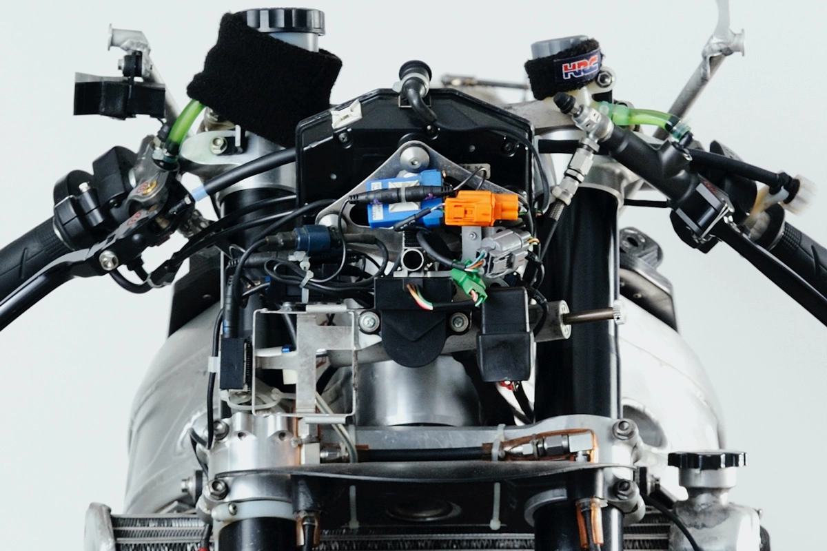
Steering damper is laterally-installed long, thin cylindrical rod-type device in the center of the photograph
To solve this problem, a rotary-type steering damper was developed. It operates by moving a vane within a damping chamber in response to the degree of steering movement, creating a damping effect as it encounters resistance from silicone oil enclosed within the chamber. With uniform operation to the left and right, this type of steering damper allowed a greater setting range because it eliminated the differences in damping characteristics experienced with the rod-type device. It also had the benefits of being smaller and lighter, enabling it to be fully incorporated within the damping mechanism case and giving it greater resistance to external impacts, such as the motorcycle falling over.
Rotary-type steering damper used from the NV5B in 2003
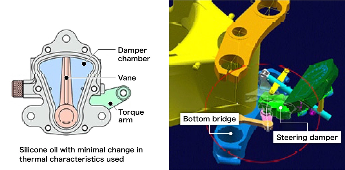
Honda originally developed the rotary-type steering damper technology in its mass production motorcycle department, but it was implemented first on the RC211V racer, which was being developed at a fast pace, and it debuted on the NV5B in 2003. From then until 2024, every Honda MotoGP machine has used rotary-type steering dampers.
Fairing (cowl) design
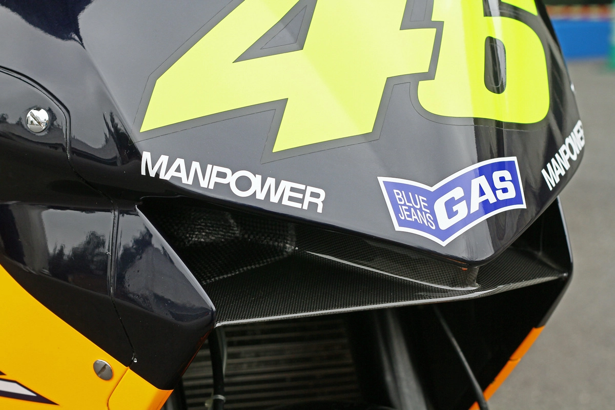
When planning the RC211V, Honda had a strong focus on concentration of mass and minimizing moments of inertia, which extended to the design of the machine’s fairing, or cowl, as well.
The greater the projected area of the side face of the chassis, the greater its aerodynamic drag in the lateral direction. This applies equally to automobiles and motorcycles, but motorcycles tilt when turning, so this side face projected area can have a major impact on agility, an important performance characteristic, when leaning the chassis over in corners. With the RC211V, Honda created a small side projected area by radically reducing the lengths of the top cowl, including screen, and seat cowl, with the aim of enabling faster leaning over in corners and, by extension, more agile handling.
2002 NV5A
While the front projected area of the top cowl was naturally small as well, this design had negative impacts on aerodynamic performance. Even when laying the upper body forward to duck below the cowl, the rider’s helmet and arms presented a large exposed area on the RC211V, creating more aerodynamic drag than the NSR500 at the time. Nevertheless, from the development stage of its first model NV5A in 2002, Honda prioritized the philosophy of achieving agile handling through a more compact cowl.
The increased drag of the RC211V, compared to the NSR500, was canceled out by an engine with output that was approximately 30% higher. And while the NV5A in 2002 had a top speed of around 320 km/h, the drag and stresses on the rider in that speed range remained high. For this reason, when designing each model from the NV5B in 2003 and thereafter, Honda continued to focus on aerodynamic development that suppressed frontal drag while avoiding loss of steering performance due to increased drag in the lateral direction.
Aerodynamic development also includes how to achieve the desired air intake for the engine, and how to direct that air to the engine. For the first NV5A in 2002, Honda provided fresh air intakes at the bottom right and left of the top cowl, but it did not fully seal the air box, where the engine intake trumpets are located, so there was no ram-air intake. However, with the need for greater engine output as the season progressed, it started to use a fully sealed air box from the middle of the season for a ram pressure boost. Cowl shape, and further evolution, from the NV5B in 2003 onward was also premised on use of ram pressure.
2003 NV5B
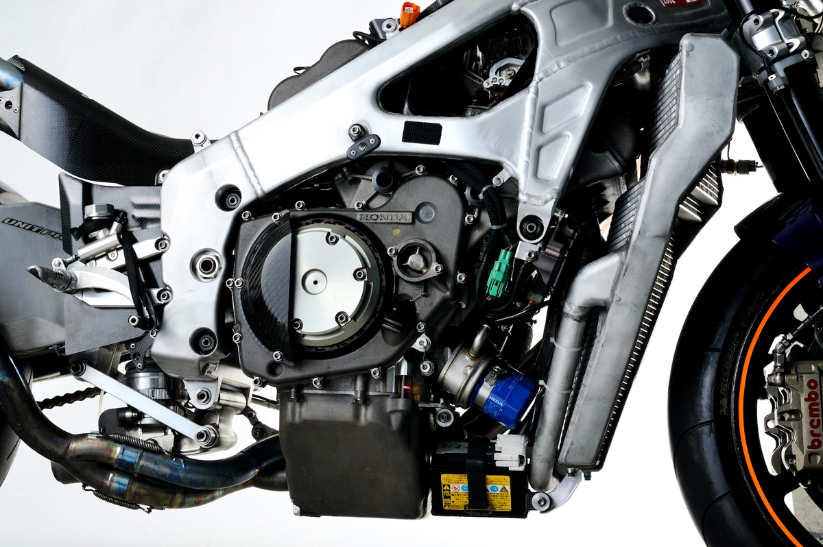
Radiator
The RC211V used an air-cooled radiator, but one with a very elaborate structure. The V5 engine used on this machine had a narrow V-angle of 75.5°, but with the front bank mounted in a forward inclined manner, there was very limited space between it and the front wheel. Nevertheless, Honda had to install a radiator in that space with sufficient cooling capacity for an engine generating around 175 kW at maximum output.
To prevent interference between the front wheel and front fork when bottomed out on its NSR500 at the time, Honda had been using a curved radiator in the shape of a large “U” for models from the late 1980s. However, that design alone did not provide the space required for a large enough radiator on the RC211V.
One day, though, one of the RC211V developers happened to see the first NR500 (NR1) entered in the Road Racing World Championship in 1979. The NR1 actually had radiators on both sides of the chassis, and to ensure sufficient airflow, the radiator cores were arranged in a stepped manner. Having seen that design, the developer decided to apply the wisdom of his predecessors to the RC211V. Working with Showa Denko (now Resonac), the company charged with manufacturing the radiators, Honda then jointly developed a water-cooled radiator with stepped radiator cores and a complex shape that clearly provided clearance from the front wheel when viewed from the side. The final result of an integrated structure, with stepped radiator cores joined in a brazing process, was truly the work of craftsmen.
2002 NV5A
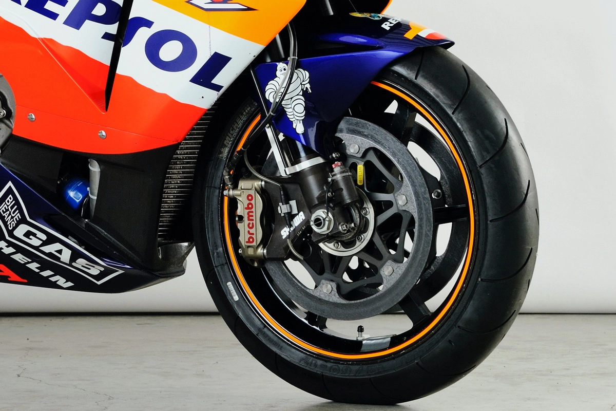
Wheels
The basic design of the RC211V wheels was inherited from Honda road racers of the 1990s. Of course, they constantly evolved as the machine’s chassis evolved, with the shape and specifications of each element (spokes, rims, hubs) being upgraded in line with requirements for things like rigidity, weight, and moments of inertia. The wheels were forged products made from a magnesium alloy, with all aspects designed by HRC and finished products supplied by Enkei.
Wheel rim size has a major impact on dynamic performance. Honda used a 17-inch front wheel rim on its first NV5A in 2002 and the NV5B in 2003, which it changed to 16.5 inches for the NV5C in 2004. While the external diameter of the tires basically remained the same, reducing the diameter of the rims increased tire height. This expanded the tire’s contact surface when leaning over in corners and improved grip stability when starting to turn after braking. The rim width was 3.50 inches for the NV5A in 2002, but Honda gradually increased the width to 3.63 inches from the NV5B in 2003, and then to 3.75 inches for the NV5HD in 2006. Naturally, this improved both grip and stability under braking.
By contrast, the standard rear wheel size for all successive generations of the RC211V remained the same, with a rim width of 6.25 inches and rim diameter of 16.5 inches. Of course, Honda continued to use rear wheels with different rim widths according to the desired setup.
As for the tires themselves, the Honda works team used Michelin tires on all of its machines in the top class of the Road Racing World Championship, starting from the debut of the NR500 in 1979. And the RC211V, over five seasons from 2002 through 2006, was no exception. While MotoGP machines were all required to run the same make of tire from 2009, tires were an area of development competition during the era of the RC211V. Actually, while the majority of motorcycle manufacturer works teams used Michelin-made tires in the MotoGP at the time, Michelin was willing to make tires to meet the individual requirements of each motorcycle manufacturer. As with other manufacturers, this was a great help to Honda.
2002 NV5A