Honda’s F1 Beginnings
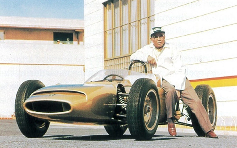
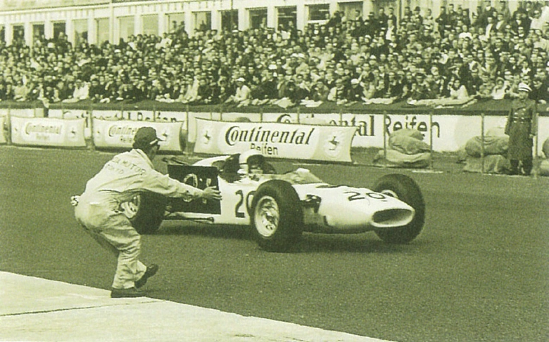
Honda first competed in the Formula 1 World Championship using a chassis and engine the company itself developed in 1964. The company had only just started manufacturing four-wheeled vehicles, having launched the T360 mini truck in 1963, the year of its 15th anniversary. Honda made its first F1 appearance on August 2, 1964, entering the RA271 in round six of the championship, the German Grand Prix. The engine was the RA271E, a 1.5-liter V12 naturally aspirated engine.
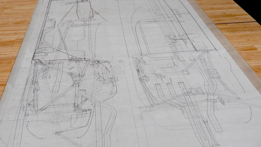
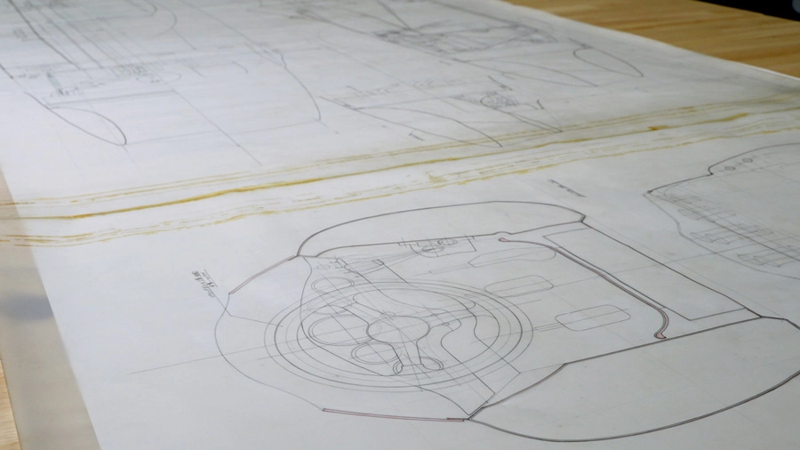
RA272: Half-Scale General Assembly Drawing
The drawing for the RA272, the chassis that brought Honda its first F1 win in the Mexican Grand Prix in the final round of the 1965 season, is still stored in its original state in the Master drawing control section*. It is a half-scale general assembly drawing showing the components of the RA272. The RA271 chassis, introduced in 1964 when Honda made its first F1 appearance, was considerably over regulation weight, so the RA272 was made dramatically lighter. The general assembly drawing shows in fine detail such things as the way the frame enclosed the transversely mounted RA272E 1.5-liter V12 naturally aspirated engine, the shift lever and linkages located to the right of the steering wheel, and the radiator positioned at the front. From things like the shape of the cowl covering the engine and the angle of the exhaust pipes extending to the rear, it is likely that this drawing was of the earlier model rather than the later one that exists today.
RA302E: Innovative Naturally Aspirated, Air-Cooled Engine
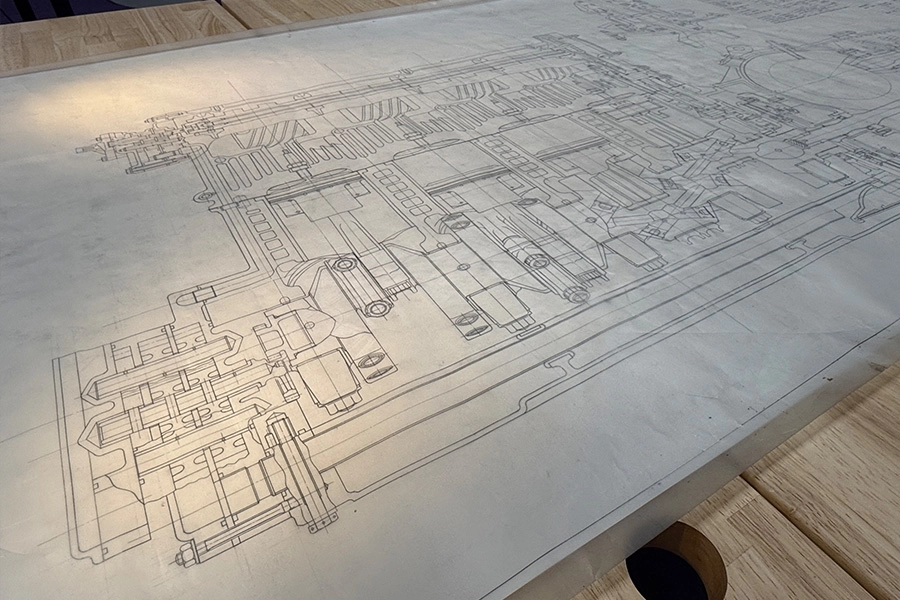
Also archived in the same way as the RA272 general assembly drawing were a series of three full-size engine assembly drawings for the RA302E. All drawings had a height of 91 centimeters, as determined by the paper standard. The width, for which there were no rules, was at the discretion of the engineer producing the drawing. At Honda, long dimensions are traditionally used for chassis-related drawings, while engine-related drawings use multiple sheets. The Master drawing control section even houses drawings 10 meters long. The RA302E drawings, created in 1968, indicate that the style of using multiple sheets for engine drawings was already established at that time.
Honda introduced the RA302E air-cooled engine in July 1968 for round 6 of the F1 championship, the French Grand Prix. Whereas the water-cooled RA301E engine, also introduced that year, was a 3.0-liter V12 engine with a 90-degree bank angle, the air-cooled RA302E was a V8 engine with a bank angle of 120 degrees. The aim was to further reduce weight and lower the center of gravity. Honda designed an F1 engine that was cooled by air. This was based on the idea that air was used to cool the cooling water for a water-cooled engine, so surely it would be better to start off with an air-cooled engine and use the air to cool the engine directly. By the same reasoning, an air-cooled engine was developed and incorporated into the Honda 1300, a small passenger vehicle launched in 1969. Technology for racing cars and commercial vehicles were linked from the outset.
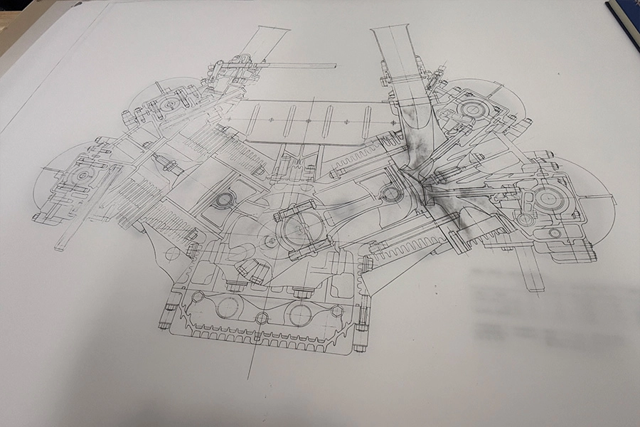
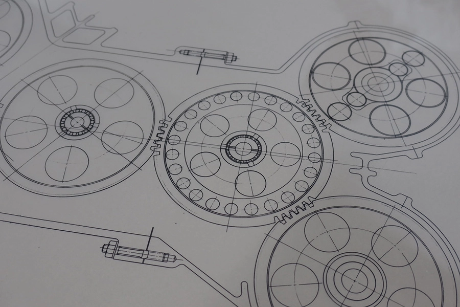
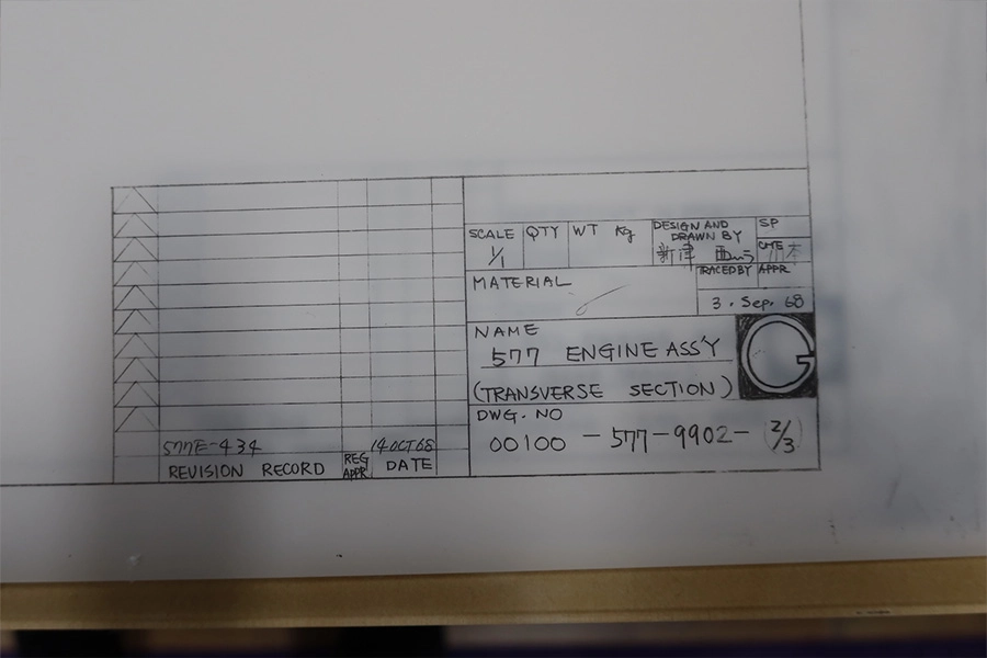
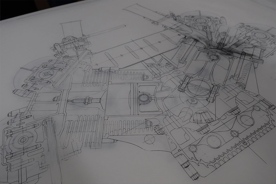
The original drawings in the archives were a longitudinal section that included a five-speed gear transmission; a transverse section; and a drawing of the timing gear train.
The drawings are dated September 3, 1968, and signed by the engineers who created the designs and the drawings. They are also signed off (approved) by a person named Kawamoto. Nobuhiko Kawamoto, later Honda’s fourth president from 1990 to 1998, was primarily involved in the design of water-cooled engines at the time. The person who created the original RA302E design was Tadashi Kume, later Honda’s third president (1983–1990). The date indicates that the drawings include improvements made after Kawamoto took over. The improved version never made it into competition.
In holes left in the original drawings where compasses were placed to draw circles, we sense the engineer living and breathing back in 1968. By changing the lead size of the pencil and the angle at which the pencil meets the tracing paper, he draws lines of different thickness and depth. The drawings are well kept, but a photocopy of the transverse section drawing comes out with darkened areas around the combustion chamber and the intake and exhaust ports. Were they smudges made by the engineer trying to work out intake and exhaust flows? Or were they the result of countless revisions? The pains that engineers went to back then are conveyed through the drawings today.
Today’s engine designers are impressed at how such a flat, small-volume combustion chamber could be designed at a time when there were no simulations. The longitudinal section drawing is like an assembly drawing and specification sheet combined as it includes a list of more than 50 specifications for the engine, such as the valve timing; the material, type of split construction, and surface finishing of connecting rods; and the maximum contact pressure for main bearings. The connecting rods and pistons for the four cylinders on one side appear like clippings from different points in time, pasted on at the discretion of the engineer who created the drawing. This would not be possible with CAD. The drawing also has the feel of a perspective illustration with the configuration of the engine parts clearly represented.
Pencil and paper have since been replaced by mouse and display, yet the act of creating a drawing (or the drawing data) today remains a means of projecting the engineer’s ideas. The essence of that shows in the original hand-drawn drawings of 1960s F1 chassis and engines.
* Master drawing control section
The Master drawing control section holds hand-drawn drawings, and also design blueprints on microfilm and other media.
Around 1986, original drawings previously held at the R&D center in Wako City, Saitama Prefecture, were all moved to the Master drawing control section, then located at the R&D center in Haga-gun, Tochigi Prefecture. Following the Great East Japan Earthquake of 2011, the Drawings Archive was relocated to a building with an earthquake-resistant structure on the premises of the R&D facility in Sakura City, Tochigi Prefecture.
Use of digital tools like CAD to create drawings gradually increased from the 1990s onward. Before then, drawings were hand-drawn. Once completed, original drawings were transferred to microfilm and stored. Photocopies of the drawings were sent to factories and elsewhere for use in production.
The task of converting hand-drawn drawings and microfilm to digital data continues to this day. The Master drawing control section still holds a number of tubes considered precious items. Among them are the original drawings mentioned in this article. Sixty years on, they spring back to life.
