
Where the fuel tank would be on a bike with a regular layout, the NV0A has four exhaust chambers. The black box next to the steering head is the fuel filter case, where the diaphragm pump sucks up the fuel from the tank under the engine and sends it to the carburetor.
The NSR500 incorporated innovative technology that was unique to the first generation.
The Problem Caused by the Exhaust Pipes Above the Engine
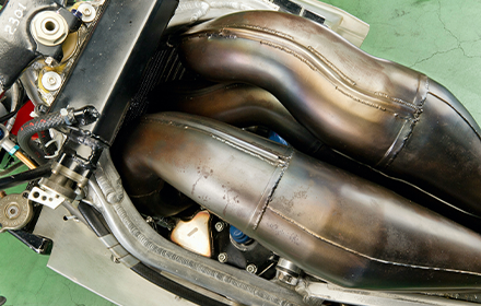
The NV0A had the fuel tank placed below the engine to lower the center of gravity, but on the other hand, the exhaust chambers had to be routed above the motor. This layout also caused various troubles.
For instance, heat was one of them. Four hot exhaust pipes are running through where you would hug with both arms when riding, so there's no way that the heat wouldn't be a problem. As a solution, HRC developed a dummy tank, in other words, a double-walled chamber shelter made of GFRP.
Installed on both sides of the upper cowl were small NACA ducts allowing outside air to take into the shelter. But there was no outlet for the heat. Therefore, in the second half of the season, they prepared a version with slits added to the upper end of the rear of the dummy tank.
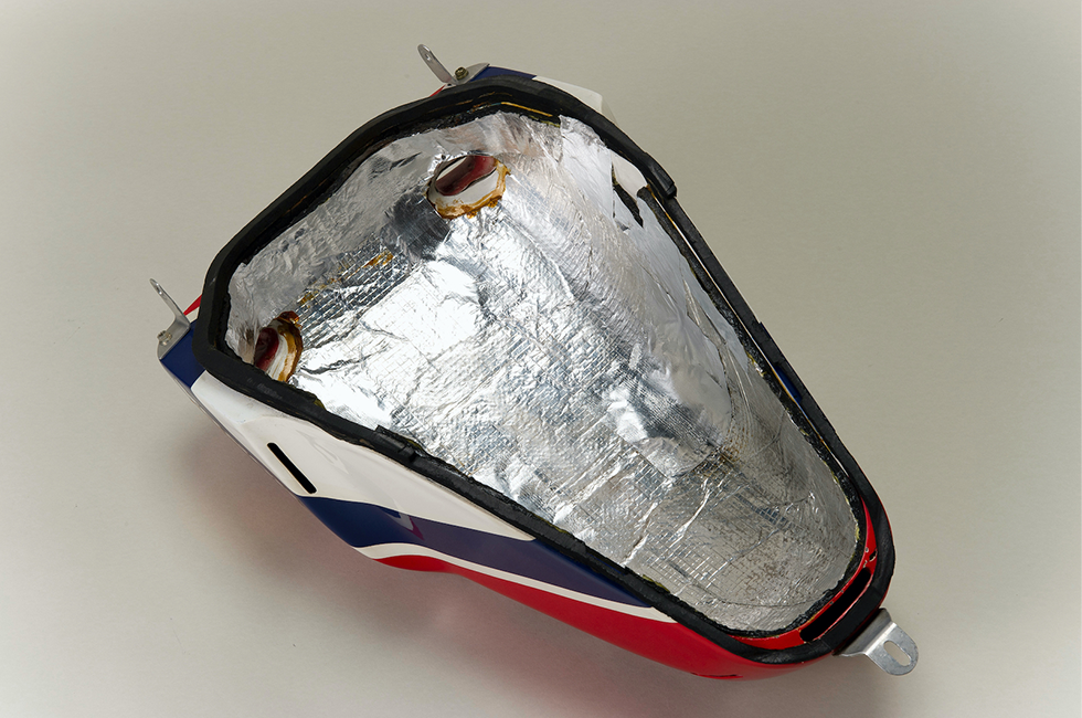
The image looks inside the dummy tank, shaped like a standard fuel tank. It has a double structure of GFRP shells with a space between them to prevent the chamber's heat from being conducted to the rider as much as possible.
Designing and manufacturing the exhaust chambers took a lot of work. The four chambers, each with their exhaust ports in different directions, had to be twisted so that their maximum expansion could fit into a space about the size of a regular fuel tank. The part of the pipe behind the mouth that connects to the exhaust port had to be bent about 90 degrees at once, and it was also necessary to find ways to prevent cracks from forming there. Besides, it took some skill to assemble the four completed chambers.
Making the Fuel Tank Under the Engine
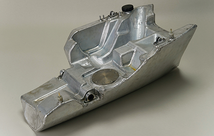
View of the NV0A's fuel tank from the diagonally rear right. To secure a capacity of 32 liters, the top of the tank has a genuinely complex shape that lines up with the bottom of the engine. It seems not easy to manufacture this tank made of aluminum plate that is molded into several pieces and then assembled by welding. The disk in the center is the cover of the service hole used for tasks such as stuffing an explosion-proof sponge into the tank. The fuel inlet is the black cap on the front left side of the central unit.
Because the NV0A's fuel tank was laid out under the engine, there were significant height restrictions, so to secure a capacity of 32 liters, they must make it as long as possible in the front and rear directions. It was also shaped like the bottom of a ship to ensure a lean angle. Incidentally, the maximum bank angle assumed when designing the NV0A was 45 degrees, which was already quite deep.
A few partition plates were installed inside the tank to suppress the shaking of the fuel. Additionally, in the center of the bottom of the tank were slopes with different heights on the front and rear. Even when fuel was low, the fuel that had gone over the slopes by the forward and backward movement accumulated in it and was sucked up. This design was unique because the tank was under the engine and could not take advantage of the free fall of fuel, unlike a typical fuel tank.
The material used was aluminum A5052P-O with a plate thickness of 0.8 mm. The tank was molded into small pieces and assembled by welding. The unit weighed 2.58 kg and was suspended from the frame in four locations: front, back, left, and right.
This particular fuel tank was the result of Shoichi Nakajima's craftsmanship. It was a complicated structure and weighed over 26kg (fuel + tank weight) when full, so it required considerable strength. There must have been a lot of hardship, but Nakajima said easily, "It wasn't that difficult. Many other tasks were more difficult than that."
The NV0A had a unique fuel path. When the fuel is sucked up from the tank under the engine by two diaphragm pumps, it enters the fuel filter case placed in front of the dummy tank, turns around there, and runs down the long delivery hose into the carburetor. The diaphragm pumps do not work unless the engine is running, so injecting fuel directly into the delivery hose leading to the carburetor before starting the motor was necessary.
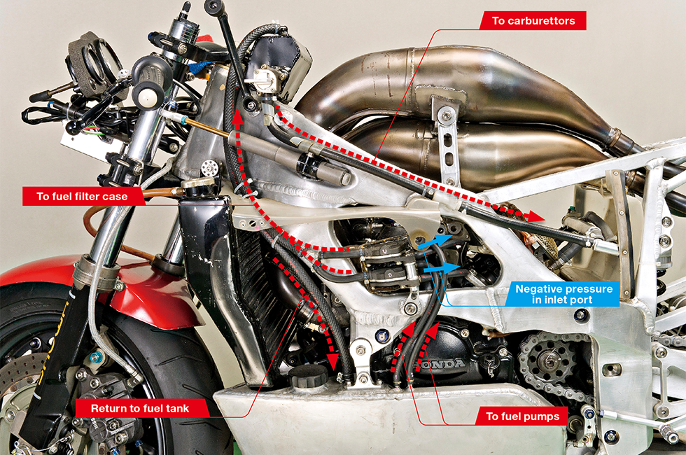
Two diaphragm pumps installed in a diamond-shaped opening between the main frame and subframe in the center of the left side of the NV0A draw fuel from the tank under the engine. The inside of the pump is divided by a diaphragm into a chamber through which fuel passes (upper chamber) and a chamber through which air passes (lower chamber.) As the diaphragm is pulled toward the lower chamber by the negative pressure from the intake manifold, fuel is sucked up from the tank into the upper chamber. Then, when the negative pressure weakens and the diaphragm returns to its straight position, fuel is pumped out of the upper chamber. Fuel is pumped from the upper chamber, enters a fuel filter case near the steering head, runs down a long delivery hose extending from there, and reaches the carburetor.


