Pursuit of Thermal Efficiency in F1 Power Units
Rather than being unrestricted, the development of power units for Formula 1 racing is governed by regulations. In 2014, the F1 adopted regulations that restricted fuel flow to a maximum of 100 kg/h to reflect the global spread of increasing environmental awareness. This meant that development had to focus on how to generate the most energy from a limited supply of fuel. In other words, it created an even greater need to pursue combustion efficiency.
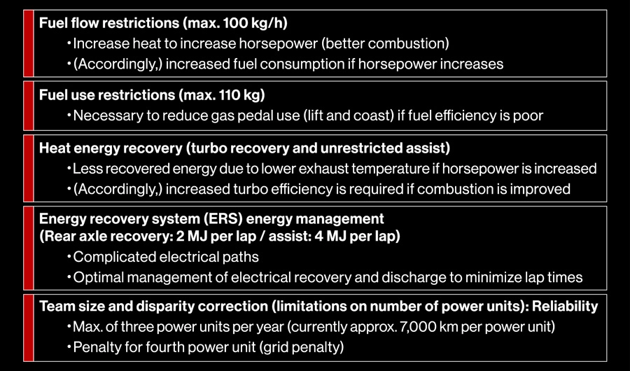
According to the fuel flow regulations, output is calculated by multiplying engine thermal efficiency by the calorific value of the fuel. In other words, the calculation shows that output increases by the amount of any improvement in thermal efficiency. These improvements in thermal efficiency can also be directed to fuel consumption.
The regulations also set maximum fuel usage of 105 kg (changed to 110 kg from 2019) for the races, which cover a distance of slightly over 305 km. Due to this restriction on fuel usage, if the engine has poor thermal efficiency, there is a double whammy of reduced engine output and an inability to drive at full throttle to save on fuel consumption.
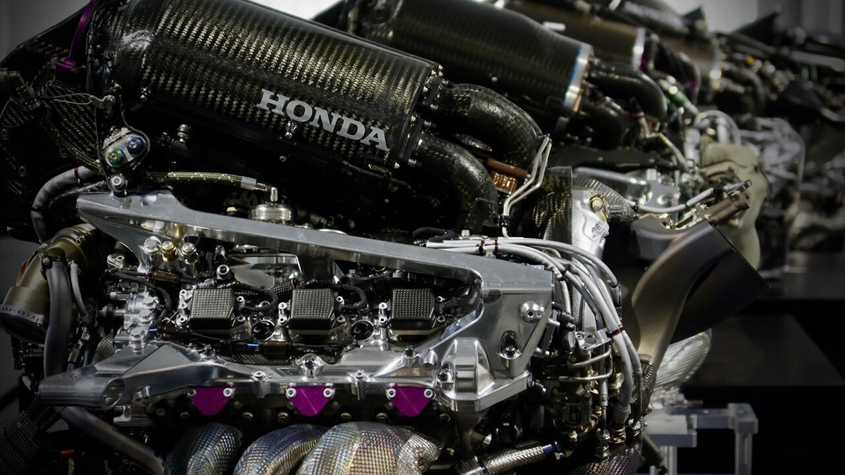
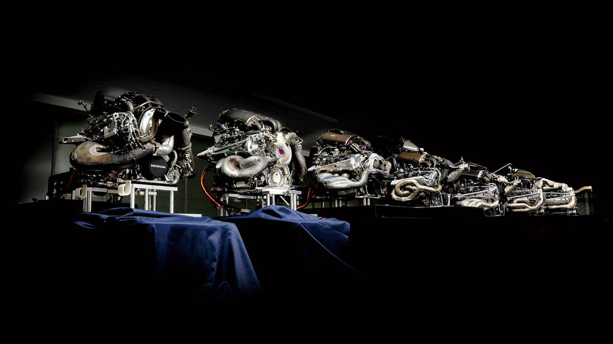
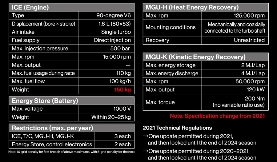
From 1964 to 1968, Honda competed in the F1 with 1.5-liter and 3.0-liter V12 naturally aspirated engines. From 1984 to 1992, it ran 1.5-liter V6 turbo engines and 3.5-liter V10 and V12 naturally aspirated engines. From 2000 to 2008, it developed 3.0-liter V10 and 2.4-liter V8 naturally aspirated engines. And from 2014, it has been using 1.6-liter V6 direct-injection turbo engines.
Compared to the 3.0-liter V12 naturally aspirated engine used in 1967, for example, the 1.5-liter V6 turbo engine used in 1988 generated about 200 kW more output. Compared to that 1.5-liter V6 turbo engine, the 2.4-liter V8 naturally aspirated engine used in 2008 generated about 30 kW more output. And compared to that 2.4-liter V8 naturally aspirated engine, the 1.6-liter V6 direct-injection turbo engine used in 2016 generated about 70 kW more output by incorporating an MGU-K (motor generator unit used for the kinetic energy recovery system) with maximum output of 120 kW.
Looking at fuel consumption when producing maximum output on the other hand, the 1.6-liter V6 direct-injection turbo engine of 2016 only consumes about two-thirds of the fuel consumption of the 2.4-liter V8 naturally aspirated engine of 2008. In other words, the power unit has extremely high fuel efficiency. The 1.6-liter V6 direct-injection turbo engine of 2016 has a dramatically lower fuel consumption rate than the 2.4-liter V8 naturally aspirated engine of 2008.
History of output improvements
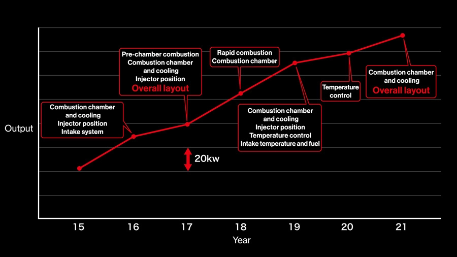
This chart plots outputs for the final specifications of each year. Lines on the vertical axis represent differences of 20 kW, showing that output increased by more than 100 kW over seven seasons. The main technical developments of each year are highlighted in each balloon, with specifications being continually optimized for compression ratios, injectors, pre-chambers, fuel pressures, fuels, and intake systems. “Combustion chamber” includes valve and plug layouts and sizes, while “temperature control” (2019 and 2020) refers to efforts to control the temperature environment for rapid combustion (self-ignition).
Lean boost
In the past, F1 engines were developed on the premise of drawing in large amounts of air and injecting corresponding levels of fuel to generate output. As explained above, the F1 set a maximum fuel flow from 2014, so development focused on efficiently generating energy from a limited supply of fuel. The typical way of achieving that aim was to improve the compression ratio and specific heat ratio.
The formula for finding the theoretical thermal efficiency of the Otto cycle shows that thermal efficiency can be improved by increasing either the compression ratio or specific heat ratio. Increasing the compression ratio to high levels sets up a battle with engine knocking, so development must focus on reducing compression end temperature within the cylinders, improving combustion speed and stability, and achieving uniform air-fuel ratio distribution. The regulations specify an upper limit of 18 for the geometric compression ratio, so the flow of development aims to get close to that upper limit.
Increasing the specific heat ratio means creating a leaner air-fuel ratio than the theoretical air-fuel ratio (λ=1). One way to improve knocking resistance and promote a lean air-fuel mixture is to use negative pressure pulsation tuning (also called lean boost).
In the age of naturally aspirated engines, development applied the theory of improving charging efficiency by using the pulsation effect of intake air. However, using the pulsation effect resulted in increased air temperature due to adiabatic compression, which was unfavorable in terms of knocking. By relying on the turbocharger to feed air to the cylinders instead, the engine could be tuned with negative pulsation drawing the air to the cylinders.
Using this negative pressure pulsation tuning effect, it is possible, through adiabatic expansion, to reduce the temperature of air entering the cylinders to a lower temperature than when it leaves the intercooler. However, it also results in a lower volume of air entering the cylinders, so higher boost pressures are required to make up the difference. The Miller cycle, which involves early closure of the intake valve, also promotes intake air cooling through adiabatic expansion.
Although negative pressure pulsation tuning and the early valve closing Miller cycle both increase resistance to knocking, a larger intercooler is required to achieve the higher boost pressures. However, because larger intercoolers impact car body performance, efficiency increases must be done with an eye on the balance with body development. Also, negative pressure pulsation tuning weakens the tumble flow within cylinders, which reduces the speed of combustion. In turn, slower combustion increases the likelihood of knocking and makes it more difficult to achieve a high compression ratio.
The following is a list of the main technologies for improving engine efficiency.
Rapid combustion
・High-tumble ports to increase turbulent flow energy
・High fuel pressure to increase atomization
・Injector spray tuning to achieve a uniform air-fuel mixture within the cylinders
・Piston crown shape tuning (recess and bowl depth)
Knocking resistance improvement (reduced compression end temperature within cylinders)
・Reduced intake air resistance (branch and port shapes)
・Optimized valve timing
・Negative pressure tuning with variable induction system (VIS)
Combustion efficiency improvement
・Lean-burn control to improve efficiency
・Reduced fuel adhesion to reduce loss due to unburnt fuel (optimized injector spray)
・Improved scavenging (valve timing)
Fuel development
・Higher calorific value
・Improved knocking resistance (fuel property changes and additives)
Control optimization
・Cylinder pressure sensors (CPS) to control knocking
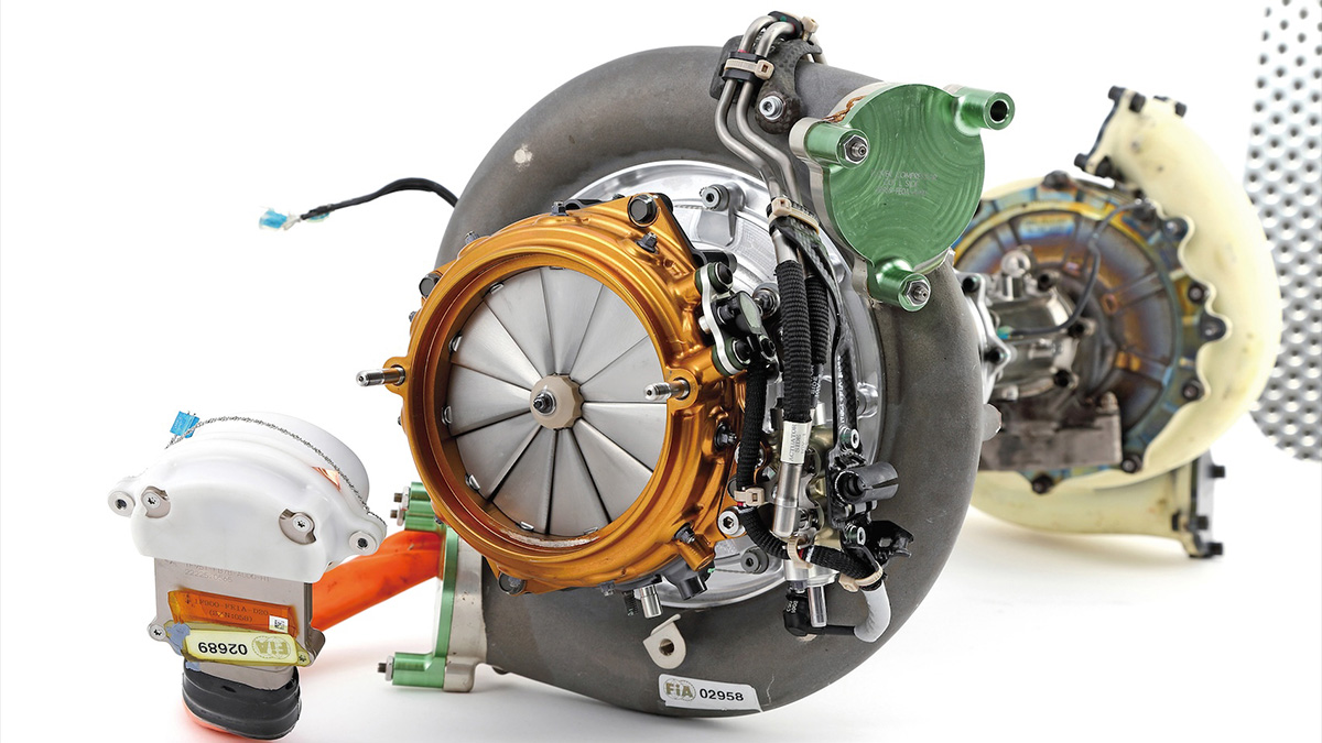
・Exhaust pressure control (using MGU-H)
Rather than being designed solely for F1 engines, these efficiency improvement technologies can also be applied to the development of mass-produced engines. One example of development targeting greater efficiency is the use of computational fluid dynamics (CFD) to optimize the shape of air intake ports. Also, as technologies that fully utilize the performance of actual engines, reliability can be ensured through continuous measurement of cylinder pressure by CPS sensors, and monitoring and control of the frequency of knocking and maximum cylinder pressure (P-Max).
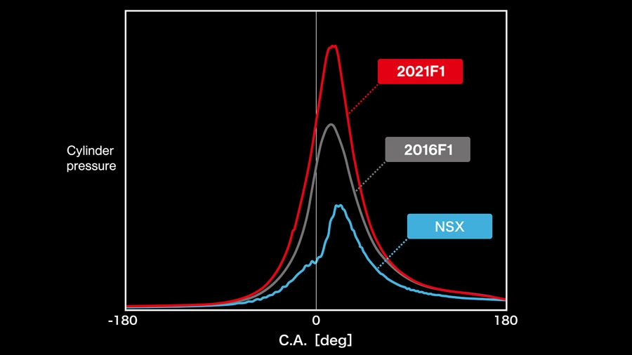
The NSX generates 389 kW of power and 600 Nm of torque, with brake mean effective pressure (BMEP) of 21.6 bar. Even in its first year of competition in 2015, the 1.6-liter V6 single-turbo F1 engine achieved almost twice the cylinder pressure of the NSX. In other words, increasing output and ensuring reliability are inseparable elements of development.
Pre-chamber jet combustion
Pre-chamber jet combustion and rapid combustion (partial self-ignition)
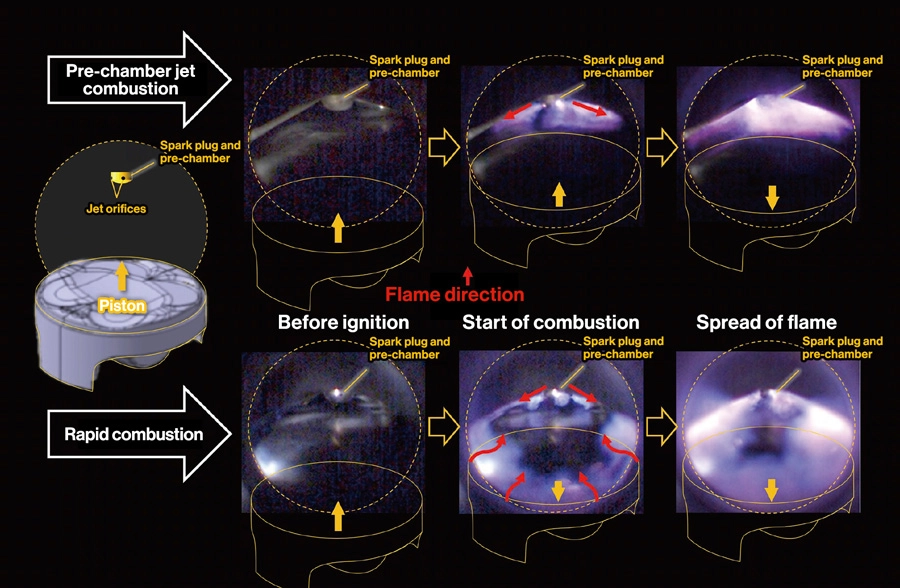
Pre-chamber combustion has been used since the RA617H in 2017. An air-fuel mixture required for ignition is injected into the pre-chamber for each cylinder, via the jet orifices, and is then ignited. Jets of fuel are then injected from the orifices to rapidly combust a lean air-fuel mixture in the combustion chamber. With rapid combustion, self-ignition around the circumference of the combustion chamber is triggered by the jets of fuel injected via the orifices. The flame propagates from the center and the outside at the same time and spreads instantaneously. (3D-printed) steel pistons have been used for rapid combustion because they are best for temperature environments that are conducive to self-ignition.
Over the period from 2015 to 2021, during which Honda produced power units for the F1, a number of technologies became major turning points in terms of improving the thermal efficiency of engines. One of those technologies was pre-chamber ignition (PCI), also called pre-chamber jet combustion, that was first used with the RA617H in 2017.
The leaner the air-fuel mixture becomes, the more difficult ignition becomes and the greater the delay in combustion. The pre-chamber jet combustion technology was applied to solve these issues. Characterized by a small pre-chamber enclosing the spark plug tip, the top of the dome-shaped pre-chamber includes multiple fine orifices. While the combustion chamber as a whole contains a lean air-fuel mixture, the pre-chamber is controlled to have a comparatively rich air-fuel mixture, around the spark plug electrode, which is ignited. Jets of fuel are then injected from the orifices into the main combustion chamber to ensure reliable and rapid combustion of the lean air-fuel mixture.
The regulations stipulate one direct-injection injector per cylinder. Therefore, instead of providing a dedicated injector for the pre-chamber, it was necessary to enable fuel sprayed by the injector, provided for the main combustion chamber, to enter the pre-chamber via fine orifices to establish within the pre-chamber an air-fuel mixture required for ignition. The challenge for development became how to achieve an air-fuel mixture for the pre-chamber while increasing homogeneity of the air-fuel mixture within the main combustion chamber. And at the same time maintaining a good balance between that pre-chamber air-fuel mixture and main combustion chamber homogeneity using the constituents of airflow and injector spray.
With the RA617H, the positioning of direct-injection injectors was changed in line with adoption of pre-chamber jet combustion. In the majority of cases for mass-produced engines, injectors are located on the inlet valve side in line with the general approach of adding fuel to an air flow to create an air-fuel mixture. Applying this approach, the RA615H in 2015 also had its injectors positioned on the intake side.
With the RA616H in 2016, on the other hand, the injectors were moved to a center position with the aim of increasing air-fuel homogeneity. Accordingly, combustion chamber shape was optimized along with the cooling structure around the injector and spark plug. With the RA617H in 2017, injector position was changed again, but to the exhaust valve side this time. This position was chosen because it was found that injecting fuel in the opposite direction to the flow of air from the open intake valve actually increased homogeneity of the air-fuel mixture.
Honda made this change because it understood the great potential of the pre-chamber jet combustion technology, but as it was still searching for that potential at the start of the 2017 season, it was unable to fully utilize its true potential at the time. With work including optimizing pre-chamber volume, and orifice size and number, it applied the optimizations as it released each new set of specifications during the season. However, the progress made from 2016 to 2017 was less than any other year when comparing final specifications for each year.
With the RA618H in 2018, Honda managed to optimize combustion chamber shape to realize the full potential of pre-chamber jet combustion at the start of the season. Furthermore, it included rapid combustion technology in Spec 3, which it introduced for the round 16 Russian Grand Prix, to significantly increase the compression ratio and excess air ratio.
Until pre-chamber jet combustion was used with the RA617H in 2017, Honda had worked to improve thermal efficiency through high-tumble combustion as an extension of the conventional technology at the time. That technology achieved combustion by generating a spark from the spark plug, which then ignited a flame that ballooned out from the spark plug electrode and spread out along the cylinder walls.
With pre-chamber jet combustion, on the other hand, jet flames sprayed from the pre-chamber spread outward to the circumference of the combustion chamber, with adjacent flames joining and slowly spreading toward the circumference of the combustion chamber where combustion is traditionally difficult. Even so, this achieved a faster combustion than high-tumble combustion.
With rapid combustion, flames are even generated around the circumference of the combustion chamber (self-ignition), where they are triggered by the jet flames injected from the pre-chamber. While the jet flames spread out to the circumference from the center of the combustion chamber, the other flames generated at the circumference spread toward the center, so combustion proceeds rapidly. As a result, the energy within the fuel is more efficiently converted to pressure, leading to increased engine output.
With the RA619H in 2019, valve geometry was optimized while fine adjustments were made to the position of the injector on the exhaust valve side, resulting in major gains. With the RA620H in 2020, development to maximize the potential of rapid combustion continued. In both 2019 and 2020, efforts were made to optimize the temperature environment for rapid combustion and self-ignition. Finally, with the RA621H in 2021, a new layout optimized to the rapid combustion technology, which generates high combustion pressures, was adopted (Evolution of the V6 Power Unit).
While developing a range of technologies that could also be applied to the development of mass-produced engines, Honda applied the combustion technologies of pre-chamber jet combustion and rapid combustion, which realized considerable progress, to its F1 power units to improve thermal efficiency through a higher compression ratio and specific heat ratio. The result was a major evolution that even made the maximum compression ratio of 18 feel restrictive despite it being an enormously high target when Honda rejoined the F1.