


-
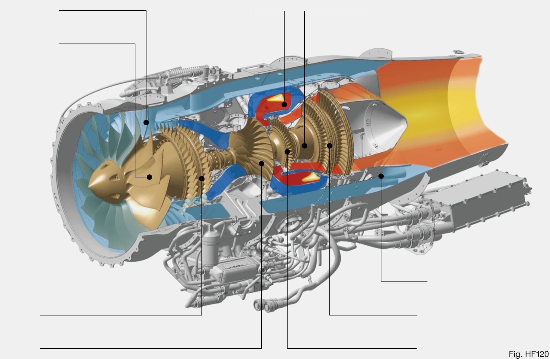
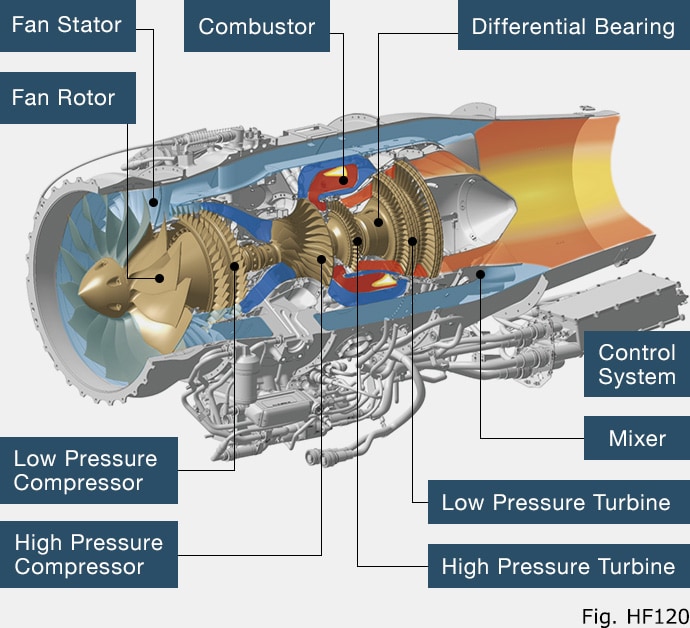
Fan Rotor & Fan Stator
The fan rotor applied the wide cord sweep design to improve the aerodynamic performance, and comprises a blisk structure in which blades and a disk are integrally cast and machined from a titanium alloy forging material for weight reduction and high strength. The fan stator also uses a carbon composite material to decrease its weight, and a metal sheet is bonded to the front edge to improve the erosion resistance.
-
Low Pressure Compressor & High Pressure Compressor
The low-pressure compressor adopts a two-stage axial flow system to improve the cycle pressure ratio and miniaturize high-pressure components while the high-pressure compressor consists of a centrifugal rotor and pipe diffuser made of heat-resistant high strength titanium alloys. The aerodynamic design using CFD (Computational Fluid Dynamics) enhances efficiency and fuel performance.
-
Combustor
The combustor is a reverse annular type to shorten the axial length of the engine. Effusion cooling with a large number of laser-drilled diagonal holes is used to cool the combustor wall, minimizing air for cooling that does not contribute to combustion, and to simplify the structure. The fuel nozzle is an air blast type that has been simplified and reduced in weight by enabling a single system to cover a wide flow rate area. In addition, by adopting the rich lean combustion method similar to CVCC, the emission regulations applied to large engines are also satisfied.
-
High Pressure Turbine & Low Pressure Turbine
The high pressure turbine employs a single axial flow stage, and by using third-generation single crystal alloys as a material for the blades, the gas temperature at the inlet of the turbine is raised. This higher inlet temperature contributes to reducing the size and weight of the engine, and improving its fuel consumption. The low-pressure turbine has two axial stages in a counter-rotation structure against the high-pressure turbine, effectively utilizing the swirling components of high-pressure turbine wakes to improve the turbine efficiency.
-
Differential Bearing
For the high pressure shaft bearing system, we applied a differential bearing system instead of a bearing system attached to a rigid frame. This design brought simpler structure and light weight.
-
Mixer
The mixer uses a lobed design to efficiently mix high-temperature exhausts from the low-pressure turbine with the low-temperature fan bypass flow, improving fuel efficiency and noise reduction.
-
Control System
The control system employs a redundant digital electronic control device called FADEC (Full Authority Digital Engine Control). Its fuel flow rate and bleed valve are properly controlled to exert thrust as intended by a pilot while guaranteeing the safety and functions of the engine under any flight conditions.
Technology
Introduction to the Structure of the HF120, the spirit of engineers who supported the technology and the quality of the HF120, and the award history of the HF120
Structure of HF120 Turbofan Engine
In addition to aiming for best-in-class ratings in terms of light weight, thrust, fuel efficiency and durability, Honda also set challenging emissions targets, despite the lack of emission requirements in the small engines for business jets, while developing HF120. To achieve the target, we combined the technology of HF118-2 and the know-how of General Electric Company (GE), and achieved the target of best-in-class performance and top environmental performance.
※ Click on the part name below to display its detailed explanation.