To deliver the ultimate in turning performance and stability, built on the outstanding dynamic performance of its all-wheel drive (AWD) system, Honda developed the world’s first Super Handling All-Wheel Drive (SH-AWD) system with the ability to freely control torque distribution between the front and rear wheels, and between the left and right rear wheels. SH-AWD made its debut on the Legend, which went on sale on October 7, 2004.
After confirming in theory that yaw moment could be directly controlled through use of a torque differential between left and right wheels to improve turning performance and stability, Honda applied the theory to its mass production vehicles through development of the Active Torque Transfer System (ATTS), which was first applied to the Prelude Type S that went on sale on November 8, 1996. The ATTS distributes different amounts of torque to the left and right wheels depending on the turning conditions, in contrast to conventional systems which could only provide equal torque to both driving wheels.
Applying greater driving torque to the outer wheel than to the inner wheel when accelerating in a turn (orbiting motion) generates a yaw moment (rotating motion) around the center of gravity. This has the effect of helping the vehicle to turn, which improves turning performance. Equipped with ATTS, the Prelude demonstrated a practical application of this concept in a front-wheel drive (FWD) vehicle.
Development of the SH-AWD technology started from the idea that performance range could be expanded by replacing AWD, which distributes driving torque between the front and rear wheels, with torque distribution to the left and right wheels. With the prospect of achieving practical application in 1989, Honda was ready to move to the product development stage, believing that better results could be produced with the AWD system, which transmits driving torque to the road surface through distribution to all four wheels.
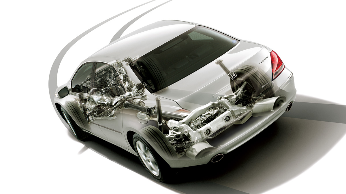
Front/rear wheel driving torque distribution (illustration)
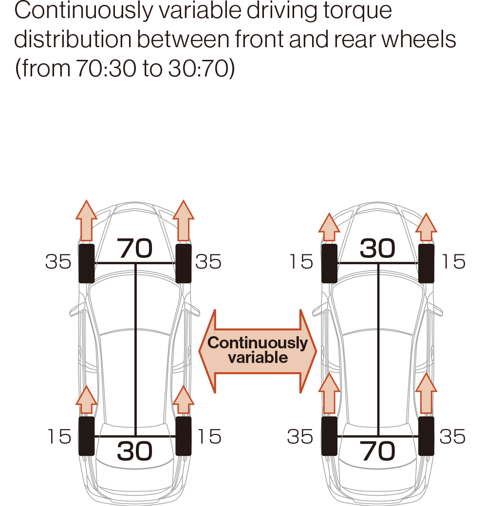
Rear left/right driving torque control (illustration)
During the development process, a number of models were studied for application of the SH-AWD system, including converting the second-generation Legend (1990–1996), a FWD vehicle with longitudinally mounted engine, into four-wheel drive (4WD). None of them made it to production. After ATTS was applied to the Prelude, the chance to achieve practical application of SH-AWD finally came around with the arrival of the fourth-generation Legend in 2004, which was equipped with a 3.5-liter V6 engine producing a maximum output of 221 kW (300 PS).
At the time, electronically controlled systems to distribute driving torque between the front and rear wheels, or to distribute rear wheel driving torque between the left and right wheels, had already been developed or implemented. However, there were no systems that could freely and variably control both front/rear and rear left/right driving torque distribution. So, what are the advantages of such a system?
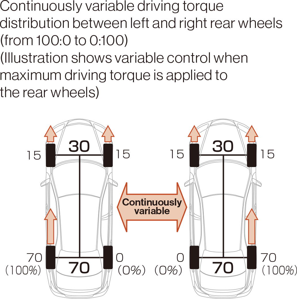
Ground load and driving torque transmission (illustration)
The ground load of each wheel (or downward force of the tire on the road surface) depends on the driving conditions. Due to load shift, outer wheel ground load increases when turning, rear wheel ground load increases when accelerating, and front wheel ground load increases when decelerating. On the other hand, the greater the ground load, the greater the force generated by the tires, meaning the greater the driving torque transmission to the road surface (the friction circle expands).
For instance, when accelerating in a left turn, transmission of the right rear wheel increases. Applying more driving torque to the right rear wheel when transmission is higher generates a yaw moment toward the inside of the turn. This force acts to point the vehicle inward. As a result, the load on the front wheels doing the steering work is reduced, understeer is suppressed, and turning performance is improved. From a different viewpoint, this makes it easier for the driver to trace the desired driving line when turning.
SH-AWD operation (illustration)
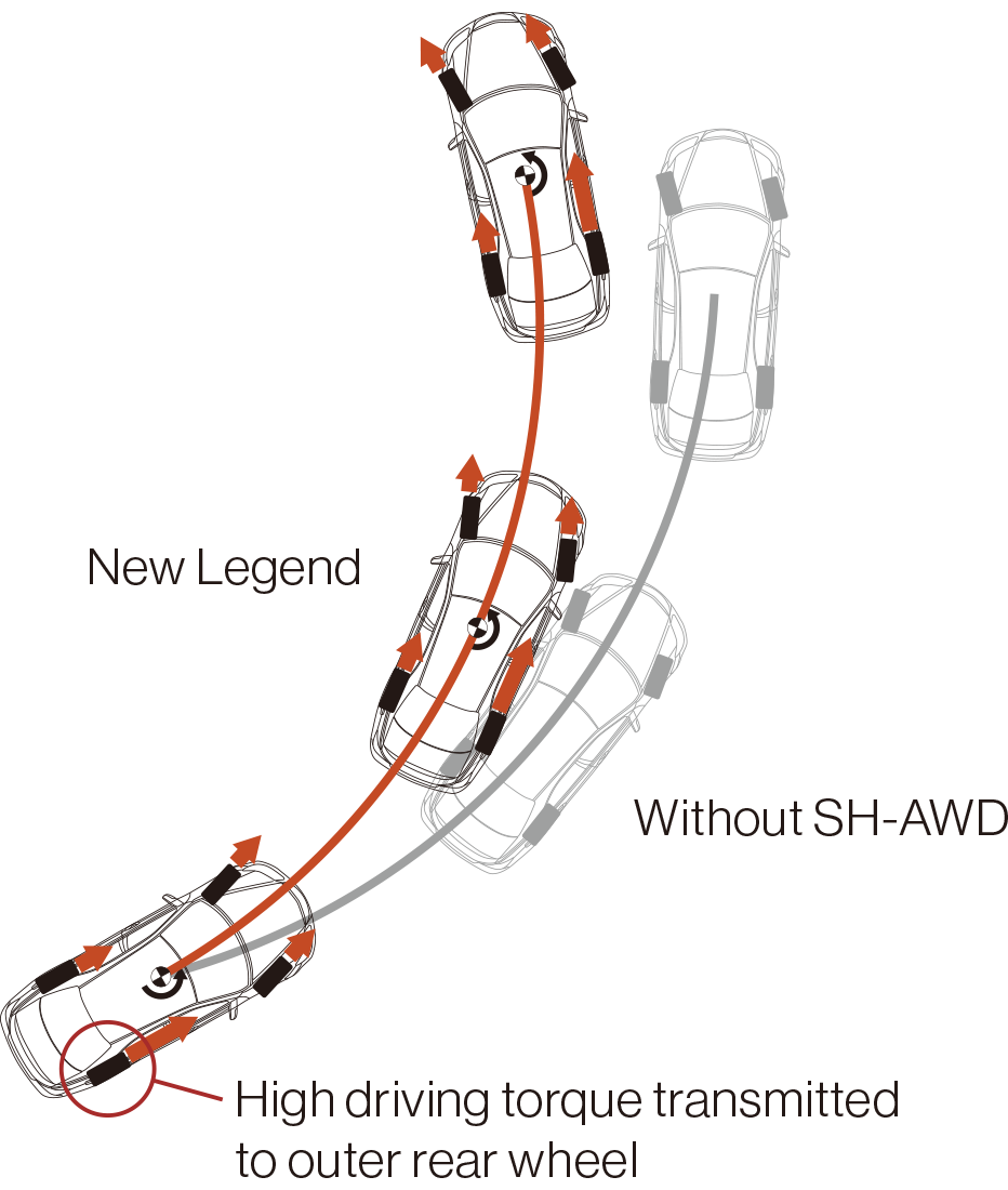
With the ability to freely control driving torque distribution between the left and right rear wheels, as well as between the front and rear wheels, the SH-AWD system applies appropriate driving torque according to the ground load of each of the four wheels to maximize the transmission of each wheel. As a result, the critical acceleration level of the turn increases and turning performance is dramatically improved. This has been proven in comparative testing between vehicles equipped with SH-AWD and 4WD vehicles providing equal driving torque to both front and rear wheels.
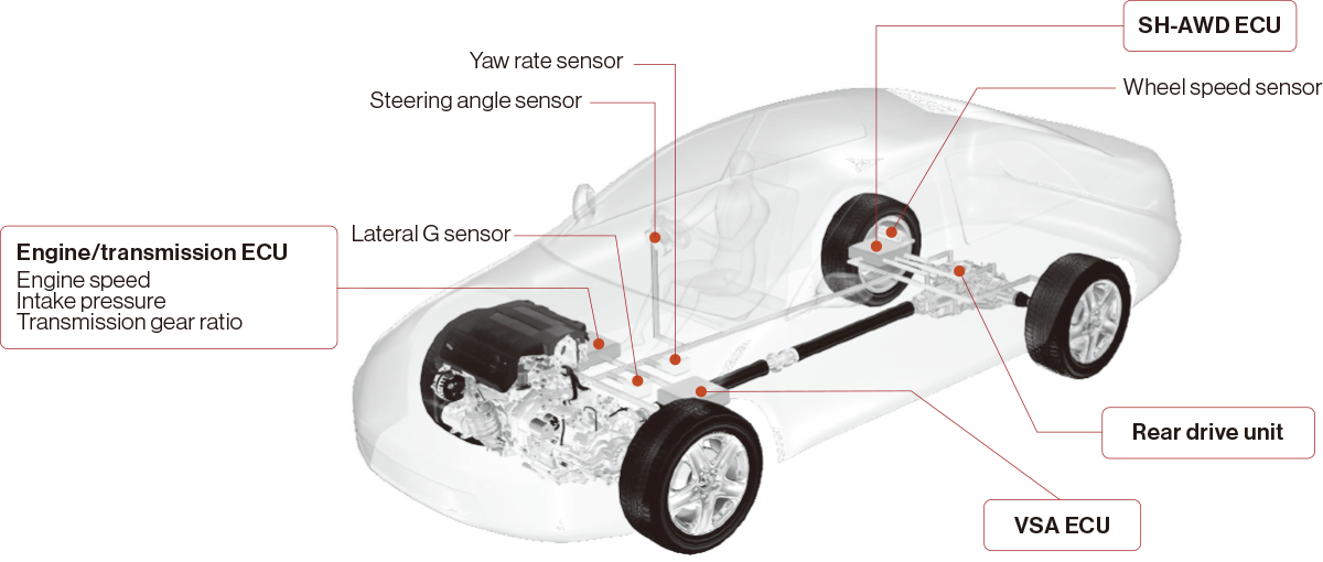
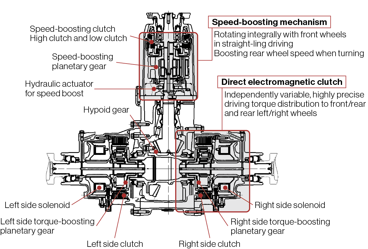
SH-AWD system configuration
SH-AWD rear drive unit cutaway model
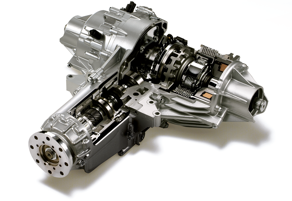
The SH-AWD system employs a rear drive unit, located aft of the carbon fiber reinforced plastic (CFRP) propeller shaft, to distribute driving torque to the left and right wheels and increase the rear wheel speed of rotation. The rear drive unit consists of a mechanism for boosting input rotation from the propeller shaft to increase speed when turning, a hypoid gear for converting input rotation from the speed-boosting mechanism into left and right wheel rotation, and left and right direct electromagnetic clutches for highly precise control of driving torque distribution. Although the system was originally developed with hydraulic multi-plate clutches, like the ATTS, they were changed to electromagnetic clutches to avoid potential breakdowns due to the hydraulic plumbing.
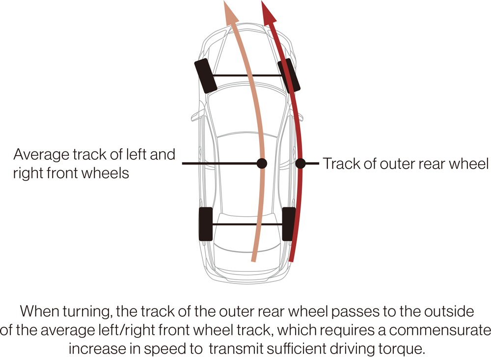
The necessity of the speed-boosting mechanism can be understood by looking at the track of the four wheels when turning. Rotational speed, which is transferred to the propeller shaft via the transfer mechanism from the front transversely mounted powertrain, is the average of the left and right front wheels. When turning, the track of the outer rear wheel passes to the outside of this average left/right front wheel track. Engaging the clutch in this situation results in the average rotational speed of the front wheels being less than that of the outer rear wheel, so the outer rear wheel decelerates and creates resistance. To avoid this, the propeller shaft rotation speed must be increased.
The difference between front and rear wheel speeds when turning depends on the steering angle of the front wheels, but calculations show that a maximum rotational speed differential of 3.8% occurs at a steering angle of 15 degrees. Therefore, considering slip rate and other factors, the speed boost was set at 5%.
Wheel track (illustration)
The speed-boosting mechanism consists of a planetary gear, one-way clutch, and hydraulic actuator. More specifically, it consists of an input shaft sun gear and output shaft sun gear with different numbers of teeth, a dual pinion with integrated pinion gears for meshing with each sun gear, a planetary carrier for retaining the dual pinion, a one-way clutch and low clutch for connecting the carrier and input shaft, and a high clutch for connecting the carrier and case.
In straight-ling driving, the low clutch engages by pressing against the low spring via the low piston. In this way, the planetary carrier and input shaft rotate integrally, making a direct connection. Rather than rotating, the pinion gears orbit together with the carrier, making it a 1:1 relationship with no rotational speed differential.
When turning, the high piston, incorporated into the case, hydraulically generates a load in response to a speed-boost signal, which presses against and engages the high clutch, compresses the low spring via the low piston, and disengages the low clutch. When the high clutch is engaged, the planetary carrier is locked to the case, the pinion gears stop orbiting and mesh with the input shaft and output shaft sun gears to commence rotating. The input shaft sun gear and output shaft sun gear have different numbers of teeth, making it a 1:1.05 relationship that generates a speed boost.
Rear drive unit structure
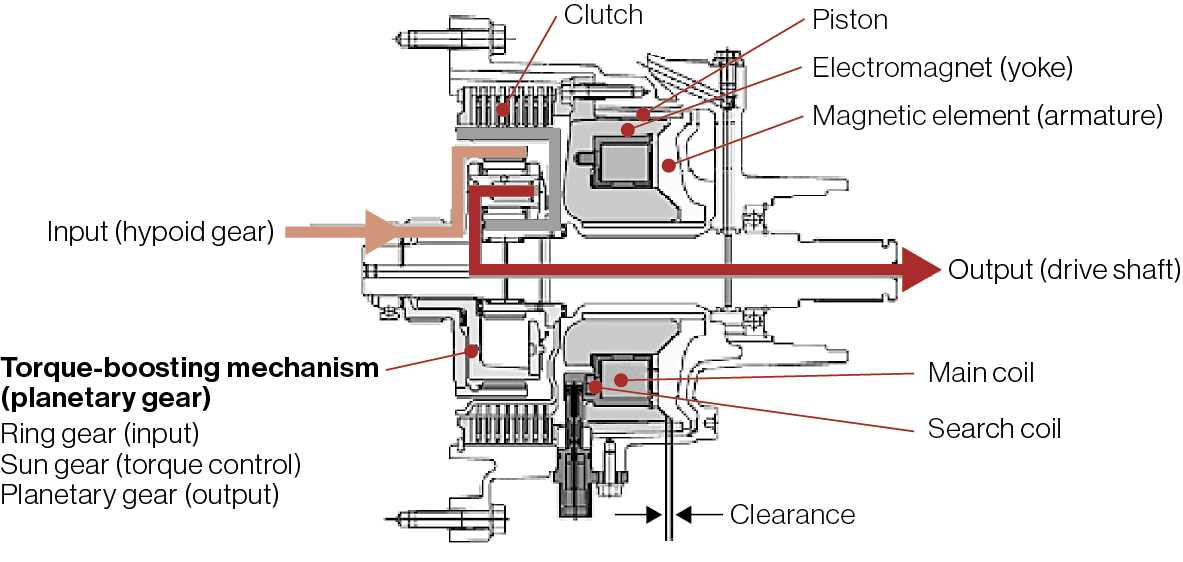
Direct electromagnetic clutch structure
The one-way clutch is assembled in a way that prevents the planetary carrier from overtaking the input shaft rotation when moving forward. The direct connection between carrier and input shaft is also retained when moving forward, which enables the low clutch, required when reversing and applying the engine brake, to be more compact. At the same time, the structure does not prevent locking of the carrier when speed is boosted. With this speed-boosting mechanism located below the fuel tank, clutch design focused on compactness to ensure sufficient ground clearance.
Front/rear and rear left/right driving torque distribution is controlled by adjusting the engaging force of the direct electromagnetic clutches to the left and right of the hypoid gear. This represents the world’s first use of direct electromagnetic clutches to directly control multi-plate clutches through electromagnetic force generated by passing a current through coils. The mechanism consists of a main coil through which a current is passed to generate a magnetic force, with the resulting electromagnet attracting a magnetic element to directly press a clutch via a piston. This pressing force can be precisely controlled by varying the current, which enables driving torque to be freely controlled.
Looking at the flow of torque, torque is transmitted from the propeller shaft, through the hypoid gear, to the ring gear. The clutch is pressed by the armature via the piston and frictional force is generated between the case and sun gear. The torque input to the ring gear is boosted by the planetary gear, and a torque proportional to the torque transmitted from the clutch is output to the drive shaft via the planetary carrier. The boosting mechanism used by the planetary gear, to create a larger force from a smaller force, has enabled the electromagnetic clutches to be more compact.
Because there is only a slight clearance between the electromagnet and magnetic element, any change in this clearance would change the current-controlled pressing force on the clutch, making it impossible to transmit precise driving torques. For this reason, search coils are used to monitor changes in the magnetic flux and current flow is corrected accordingly to achieve highly precise driving torque control for the life of the vehicle.
SH-AWD control logic
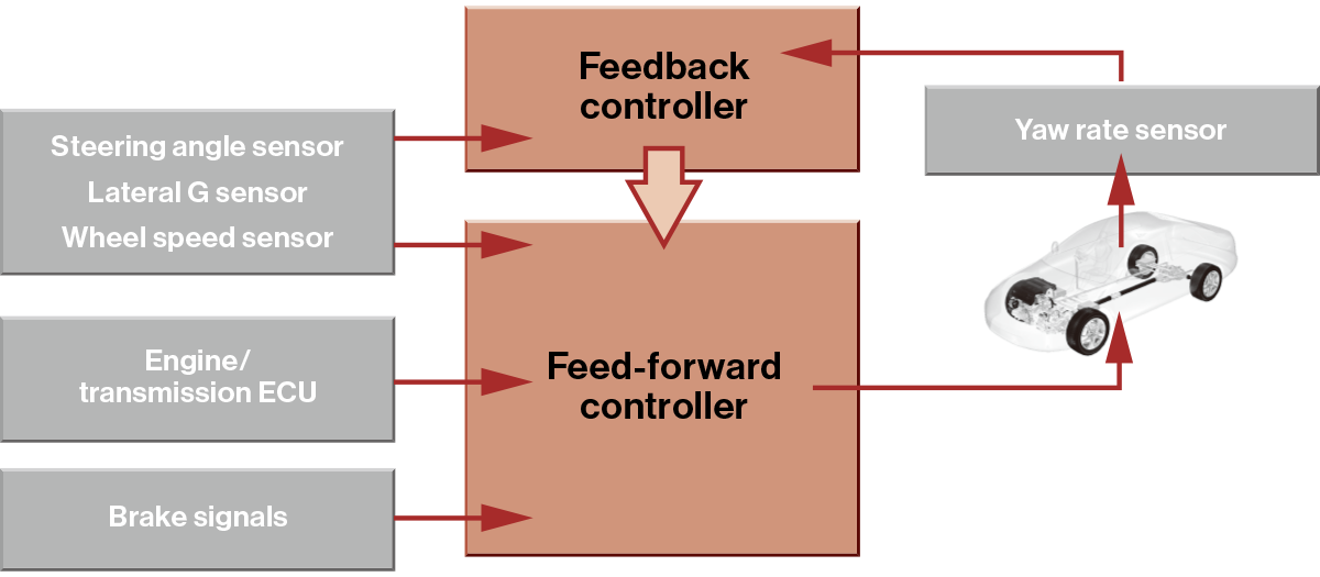
With the aim of respecting driver’s intent to the fullest, the SH-AWD system’s driving torque control logic operates mainly on feed-forward control based on driver input. The control flow is explained below.
Driver input (driving operation) is estimated from the amount of movement of the gas pedal and steering wheel, and brake signals.
● Engine torque is estimated from the preset torque map using engine speed and intake pressure, etc.
● Engine torque is converted to total axle driving torque using the transmission gear ratio and torque converter torque ratio, etc.
● The torque distribution ratio between the front and rear wheels is set according to the driving state, including vehicle speed, transmission gear ratio, and throttle angle.
● Rear wheel torque is calculated from the total driving torque and front/rear wheel torque distribution ratio.
● The turning amount is calculated from lateral acceleration (estimated from rear wheel average speed and steering angle), the lateral acceleration sensor, and yaw rate sensor.
● Individual driving torques for the left and right rear wheels are calculated based on the turning amount.
● Driving torques are output to the left and right rear wheels as set currents to each electromagnetic clutch.
Due to the possibility of reduced precision of control caused by changes in vehicle behavior or changes in road conditions, the following feedback control flow is also used to correct the control logic.
Slip angle is estimated at the vehicle’s center of gravity, which depends on the frame model.
● Estimated slip angle is compared with the threshold slip angle according to the turning amount, and if slip angle is determined to be too great, the rear wheel left/right torque differential obtained through feed-forward control is reduced, and corrected control is output.
● If slip angle is still not reduced, corrected control is output to reduce the torque distribution ratio to the rear wheels.
The SH-AWD system transmits driving torque to all four wheels, with a distribution between the front and rear wheels and a distribution between the left and right rear wheels. In this way, it is able to maximize the performance of each tire in all driving conditions while also improving turning performance. This system has enabled Honda to create cars that, more than ever, feel like they are behaving at the will of the driver.