Honda has been taking a multifaceted approach to address the global environmental challenge of reducing CO2 emissions from its products and corporate activities. Honda was one of the first companies to recognize the potential of hydrogen and has been conducting research and development of fuel cell technologies for more than 30 years. By advancing its fuel cell system, Honda will establish a “hydrogen circulation cycle” along with a “electricity circulation cycle” and a “carbon circulation cycle,” which Honda will pursue to realize carbon neutrality by 2050.
Combining hydrogen and fuel cells for stable use of renewable energy
Every year, Honda produces approximately 30 million units of a diverse range of power units installed to a variety of Honda mobility products. Honda has been pursuing carbon neutrality by applying the right technology in the right places and for the right purpose, so that energy use by its power units can be optimized depending on how and where they are used.
To be more specific, Honda is envisioning the use of electricity derived from renewable energy sources for short-distance mobility products, and the use of hydrogen with high energy density for long-distance, heavy-duty trucks. For aircraft and ships, which are difficult to electrify, Honda is envisioning the circulation of energy through the “carbon cycle,” using renewable fuels converted from atmospheric CO2.
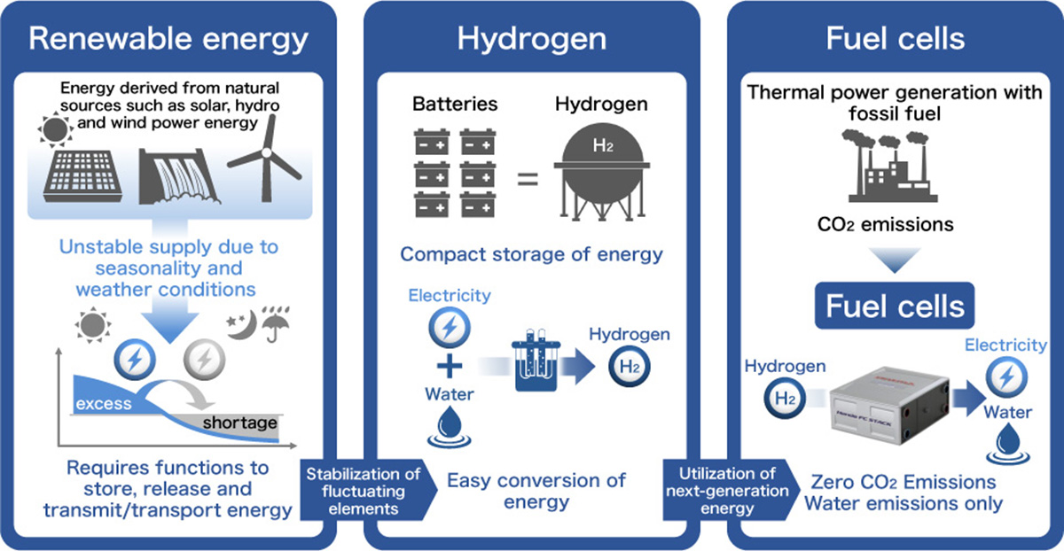
To achieve carbon neutrality, it is necessary to stabilize the supply of renewable energy, which is more susceptible to seasonality and weather conditions. Due to its unique features of high energy density and ease of energy conversion, hydrogen is attracting attention for its role in making adjustments to the amount of surplus electricity. Fuel cells can convert hydrogen into energy without emitting any CO2 and other greenhouse gases; therefore, by combining with hydrogen, fuel cells can generate electricity without causing any environmental impact.
Image of the stable utilization of renewable energy with the use of hydrogen and fuel cells
Steady advancement of Honda fuel cell technology, realizing both high output and compact size at the same time.
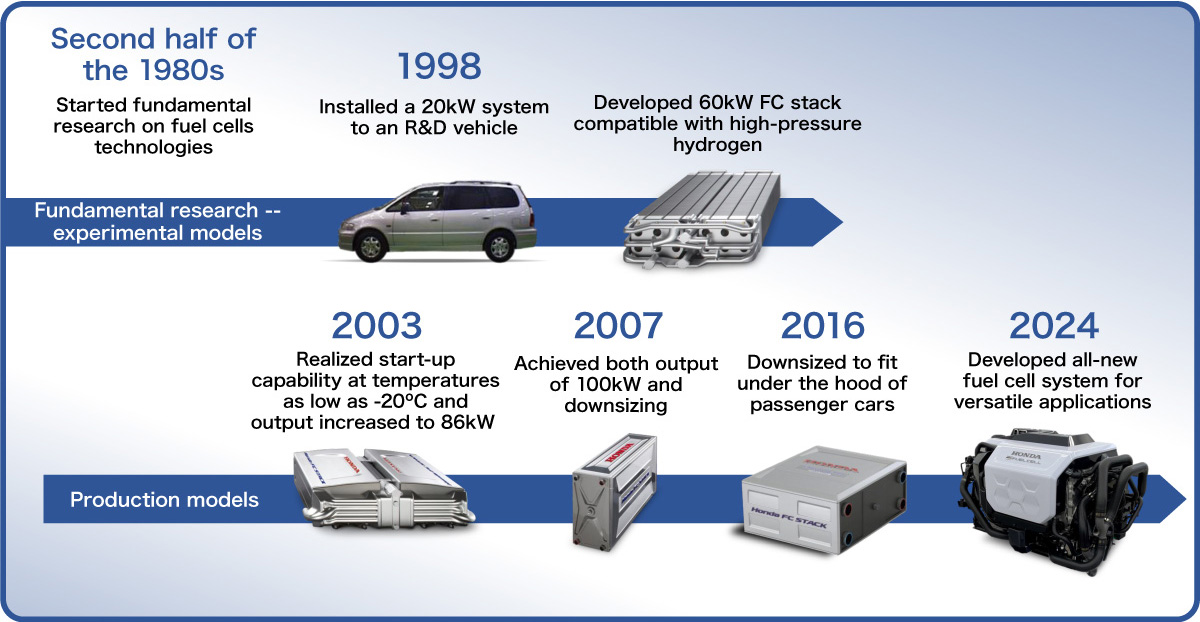
Honda began fundamental research on fuel cell technologies in the second half of the 1980s and developed a prototype fuel cell vehicle equipped with a 20kW fuel cell system in 1998.
Honda kept making steady technological advancements to further improve the performance of its fuel cells, including the high efficiency and high output, and launched an experimental vehicle equipped with a 60kW fuel cell system in 1999, and announced the Honda FC Stack, which was capable of starting at sub-freezing temperatures as low as - 20ºC (-4ºF) in 2003.
In 2007, the FCX Clarity was introduced to the market featuring 100kW high output and a 4-seater sedan packaging that was realized with the downsizing of the fuel cell system. In 2016, Honda launched the Clarity Fuel Cell, the world’s first*1 FCV that featured a fuel-cell powertrain small enough to fit under the hood.
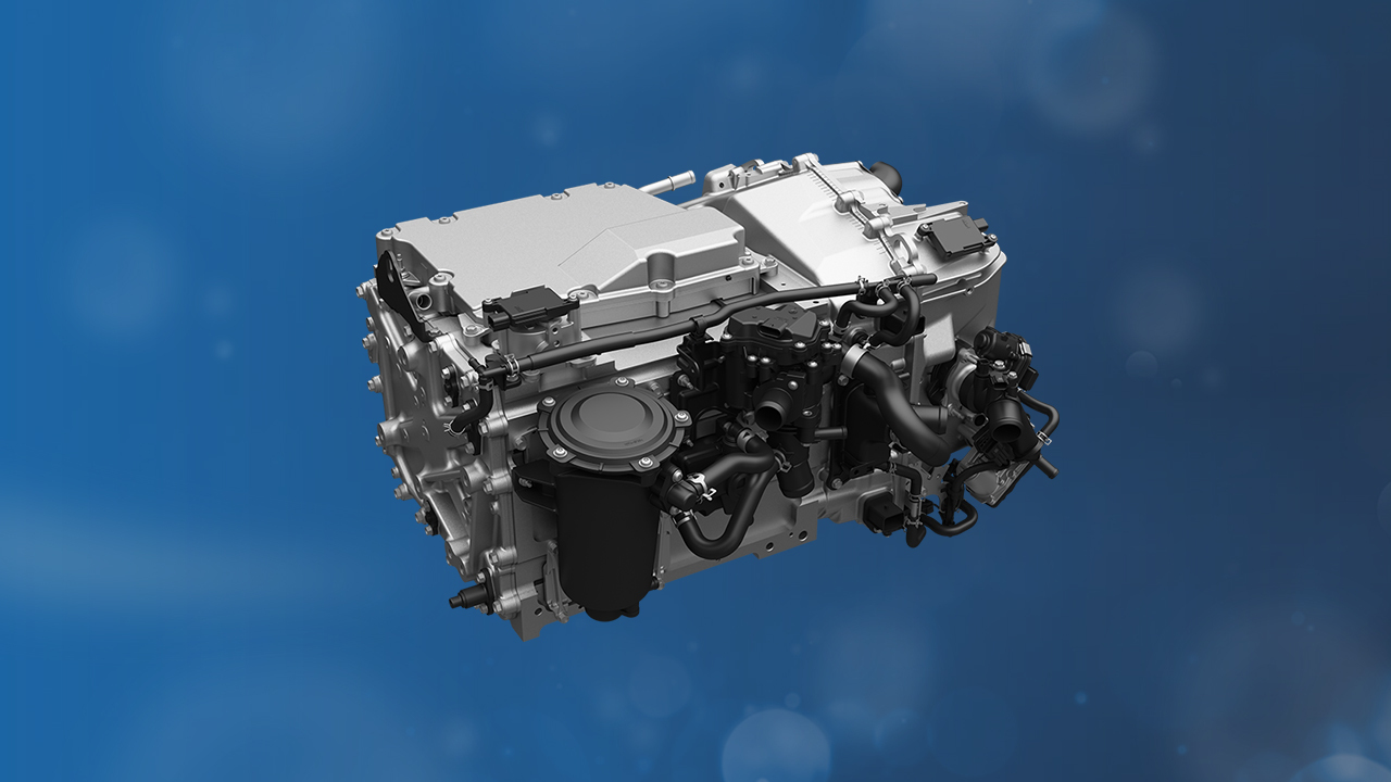
Then, jointly with General Motors (GM), Honda developed and produced the all-new next-generation fuel call system, which can be used not only for passenger vehicles but also a wide range of applications.
*1 Among sedan-type planned production models. Honda internal research (as of February 2016).
Advancement of Honda FC Stack
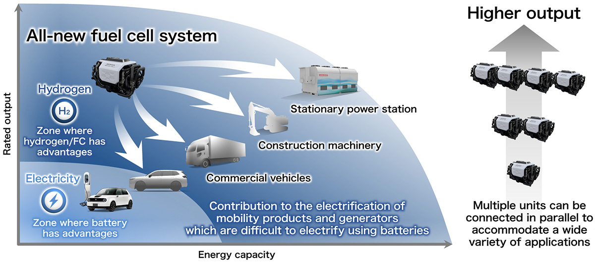
Because hydrogen is characterized by its ease of storage and transportation and short filling time, it is expected to be utilized in domains where electrification with the fuel cell system is suitable, such as 1) heavy-duty trucks that require long range, 2) backup power sources which are increasingly in demand from the perspective of business continuity planning (BCP), and 3) heavy construction machinery with long operating hours.
Moreover, the fuel cell system can be applied to large-sized commercial vehicles and megawatt-class stationary power stations by connecting multiple units and realizing higher output. This feature enables the fuel cell system to contribute to efforts to achieve carbon neutrality commercial transportation and industrial machinery and equipment.
Versatile applications of the all-new fuel cell system
The pursuit of cost, durability and low-temperature resistance, which are the keys to the widespread use of fuel cells.
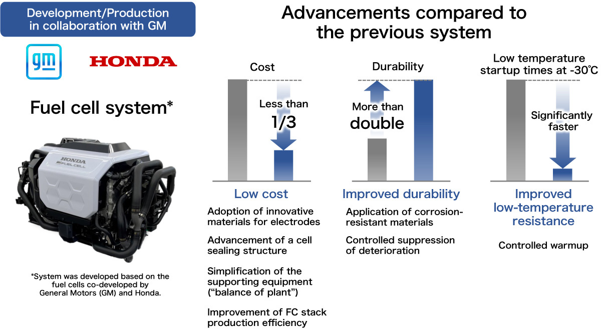
For versatile applications of fuel cells, in addition to excellent performance such as high output and ease of installation, low cost and high durability which enable long-term use for various applications will be important. Therefore, Honda and GM co-developed the new-generation fuel cell system while leveraging the knowledge, know-how and economies of scale of both companies.
By implementing various measures such as elimination or reduction of the use of expensive materials realized by the rationalization of the system structure and an improvement of productivity in stack production, the cost of the fuel cell system has been reduced to less than one-third of the cost of the fuel cell system used in the Clarity Fuel Cell. Moreover, the durability of the system was more than doubled by the application of corrosion-resistant materials and high-precision deterioration suppression control technology, and startup performance in a low-temperature environment was further enhanced.
Advancement of the all-new fuel cell system
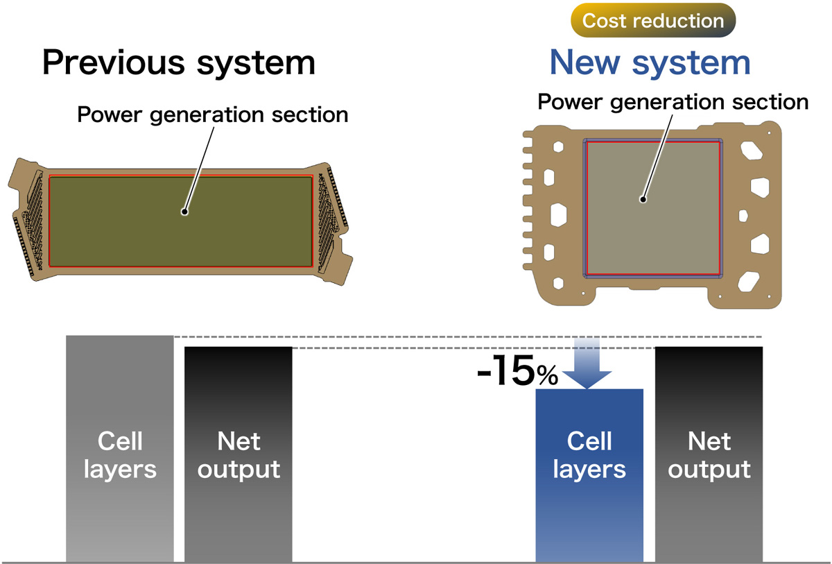
A fuel cell system generates high output by connecting several hundred cells, which are individual power generation units, in series. To achieve significant cost reduction, the development team strived to reduce the number of cell layers without lowering the net output, which is the output that can be extracted from the system. To this end, the output per individual cell was increased by optimizing the area of the cell’s power generation section, and the power consumption of the supporting equipment (“balance of plant”) was thoroughly reduced. The lower cost was achieved by reducing the number of cell layers by approximately 15% compared to the previous system, while achieving the same net output as the previous system.
Reduction of the number of cell layers
In order to secure the net output equivalent of the previous system while reducing the number of cell layers, the team thoroughly rationalized the supporting devices that consume power generated by the fuel cell system. By making full use of model estimation, a number of devices were replaced or optimized with the ECU-controlled alternatives and through changes in operating conditions, which contribute to cost reduction.
Advancements of air supply system:
<Cost reduction>
●The structure of the electric turbo air compressor was simplified from the previous 2-stage compression to 1-stage compression by increasing rotation speed of the compressor by 1.5 times.
●The humidifier bypass valve was eliminated as the stack became capable of operating at high humidity.
●The EGR pump was eliminated through the adoption of a new control technology.
<Improvement of low-temperature resistance>
●When the ambient temperature is low, the water-cooled intercooler warms up intake air to reduce water (dew) from the condensation that forms at the inlet of the stack and improves low-temperature start-up performance.
Advancements of hydrogen supply system:
<Cost reduction>
●Hydrogen pump was eliminated due to improved hydrogen displacement performance through pressure boost control during startup.
●Temperature/water level sensors were eliminated by replacing them with temperature prediction and produced water volume estimation control based on data obtained by other sensors.
●The pressure switching valve and secondary regulator were eliminated by adopting a chamber and optimizing the injector mounting structure.
The Honda fuel cell system features fuel cells with solid polymer membrane, and each cell consists of 1) electrode assembly in which a solid polymer membrane (electrolyte membrane) is sandwiched between a hydrogen electrode and an air electrode and 2) separators (bipolar plates) that form the flow paths for hydrogen, air and coolant. Each cell functions as generation unit, and fuel cell stack (FC stack) consists of layers of individual cells. For the new fuel cell system, the development team revamped the whole system starting with the cell structure, which is the core of the fuel cell.
Image of power generation by a fuel cell

Image of power generation unit
The cell featuring a new, simple structure
In the previous system, one cell unit consisted of three sheets of separators and two sheets of electrode assembly (membrane electrode assembly, or MEA).
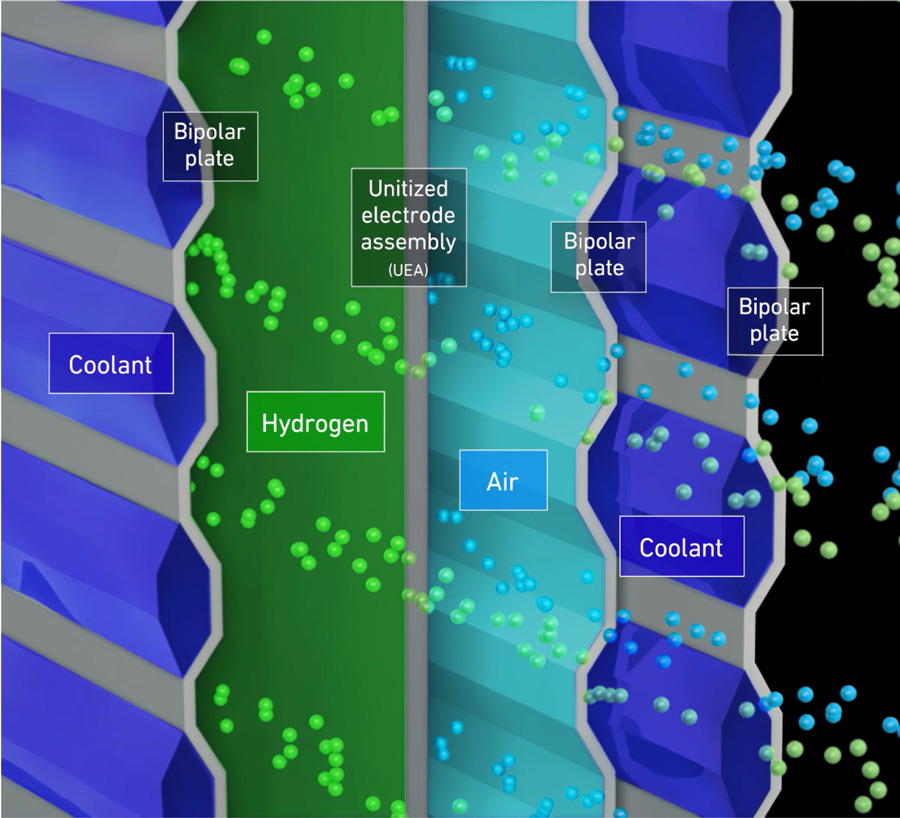
Now, in the new system, the cell structure was simplified to consist of one sheet of separator (bipolar plate) that welds two plates together and one sheet of electrode assembly (unitized electrode assembly, or UEA) per unit.
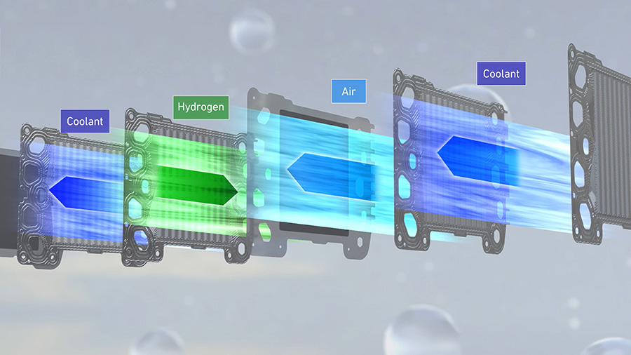
A flow path for coolant is formed inside the bipolar plate, and the flow path for hydrogen and air is formed between the bipolar plate and the UEA. This new structure enables cooling of each cell, instead of cooling of every two cells adopted for the previous cell, and cooling performance was further improved by optimizing the aspect ratio of the cell, which led to a further increase in durability.
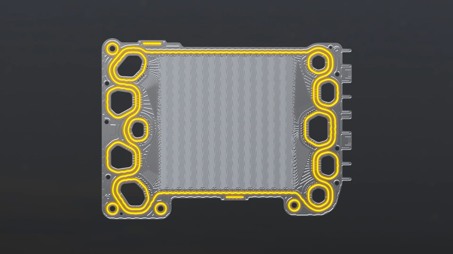
Moreover, whereas the previous system required flow path structures on both the separator and the plastic frame of the MEA, the new system consolidates the flow path structures on the bipolar plate, allowing the UEA plastic frame to have a simpler structure, which contributes to the rationalization of material costs.
Structure of a cell unit
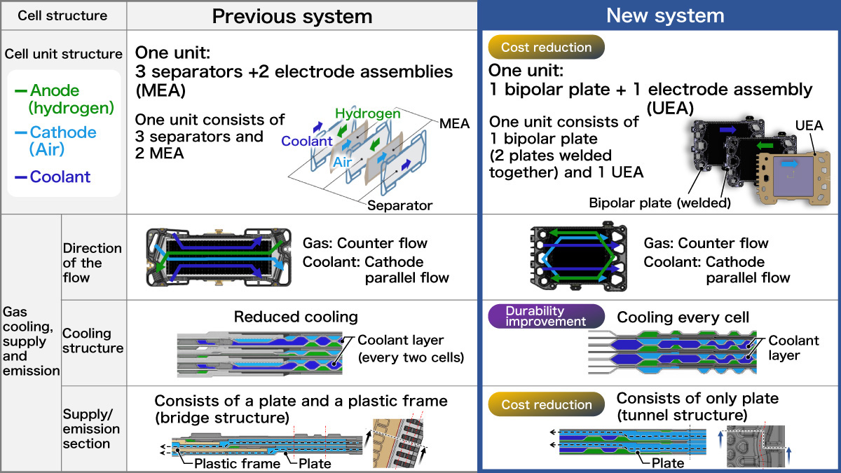
Image of cell unit structure
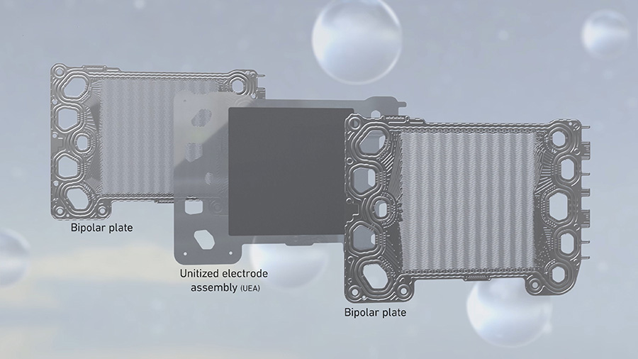
Image of flow path configuration
Realizing new-structure separator with high-precision welding technology
Because coolant flows through the hollow between the two welded plates, the separators require extremely precise welding technology. Applying the high-precision laser welding technology co-developed by Honda and GM, a new-structure separator, with two metal plates welded together, was newly developed.
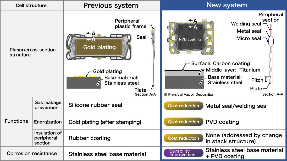
Moreover, since the UEA is sandwiched between two bipolar plates to form flow paths for hydrogen and air, cell sealing performance is critical for the new fuel cell system. For the previous system, silicone rubber was molded onto a special metal plate to ensure sealing performance using the elasticity of the rubber.
On the other hand, the new system uses a more common metal, and the elasticity of the hollow spring structure formed by the two plates is used for sealing. Furthermore, the micro seal is screen printed to ensure even higher sealing performance.
To ensure electrical conductivity, instead of applying gold plating for the entire surface, a new film formation method was adopted, which uses physical vapor deposition (PVD) coating to deposit carbon on top of a highly corrosion-resistant titanium layer. Coating titanium and carbon before stamping enabled continuous processing, which improves productivity that contributed to the lower cost of the new fuel cell system.
Structure of the separator
Honda original laser welding technology
Enhancing durability through changes in materials and production method
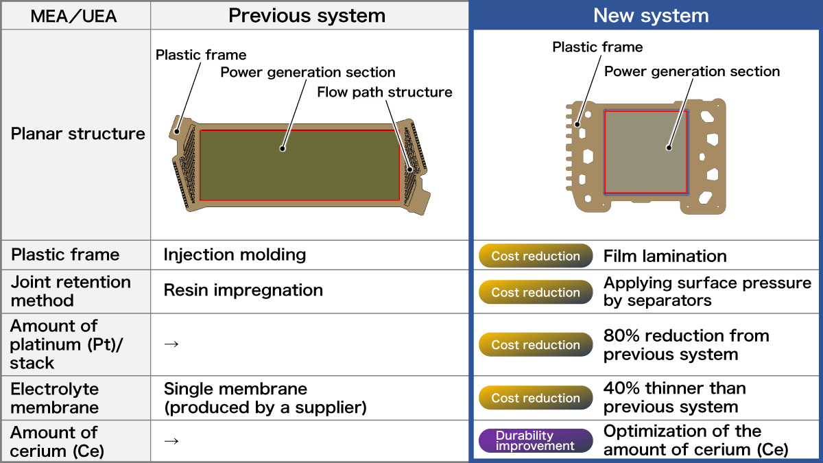
By consolidating the flow path structures on the separators, it was no longer necessary to form flow path structure on the plastic frame of a UEA. Therefore, the precision injection molding of expensive engineering plastics was replaced with the die cutting of plastic film as the method to form the UEA plastic frame. Moreover, production efficiency was increased by eliminating the impregnation process by applying surface pressure by separators to hold the joints of the plastic frame. Furthermore, by increasing the precision of humidity control, the durability of the cell was increased, and the use of platinum was reduced by 80% compared to the previous system.
The production process of the electrolyte membrane was also reviewed. By forming the membrane from the liquid material and applying the catalyst at the same time, the base film, which was an auxiliary material that was previously required, was no longer required, and the membrane thickness was reduced by 40% compared to that of the previous systems, which reduced the cost through both reduction of materials used and the improvement of production efficiency. Additionally, durability was further improved by increasing the use of cerium and neutralizing side-reactants from water electrolysis, which is one of the causes of the deterioration of the electrolyte membrane.
Structure of MEA/UEA
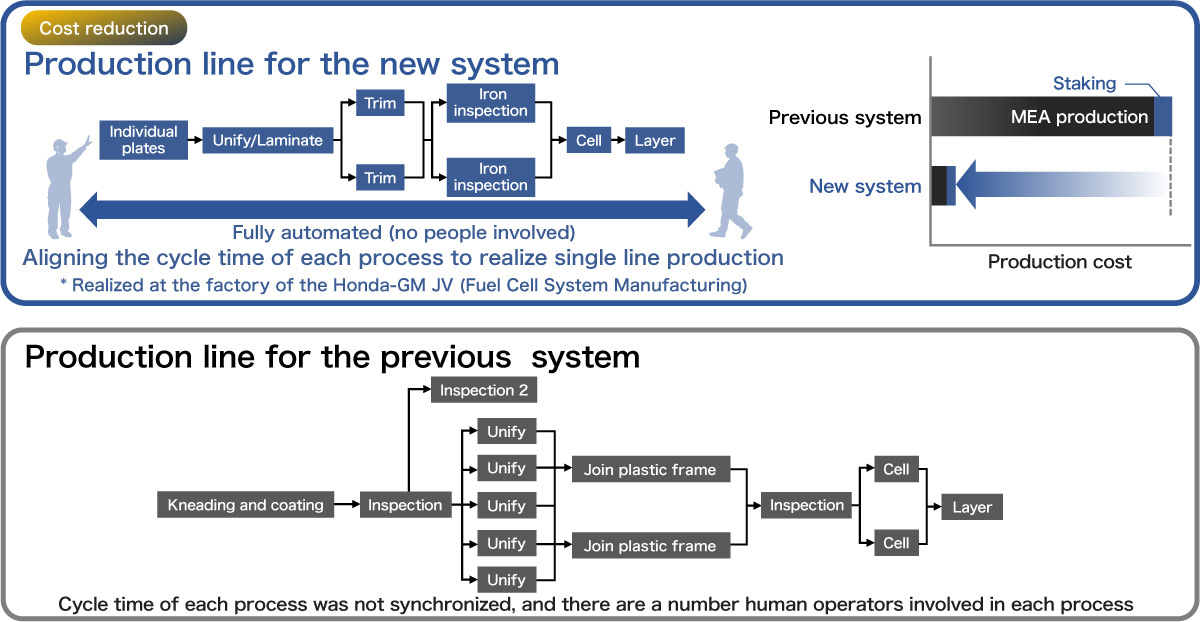
Significantly increasing production efficiency with the adoption of a fully automated high-speed production line
The new FC stack is being produced by Fuel Cell System Manufacturing, LLC, a joint venture between Honda and GM. The FC stack consists of several hundred cells stacked together, and each and every cell must meet the high production quality level. By aligning the cycle time of each process and realizing continuous production, the overall production cost was significantly reduced compared to the previous version of the FC stack.
High-speed production line
Achieving stable power generation by controlling humidity and temperature with extreme precision
The electrolyte membrane that allows hydrogen ions to pass through to the air electrode side has the characteristic that an increase in the humidity level, increases its permeability (power generation efficiency). However, if water remains on the power generation surface, it narrows the air flow path and reduces power generation efficiency. In order to maintain the appropriate humidity, it is necessary to adjust the temperature of the cell and carefully control the amount of evaporation of the surrounding water.
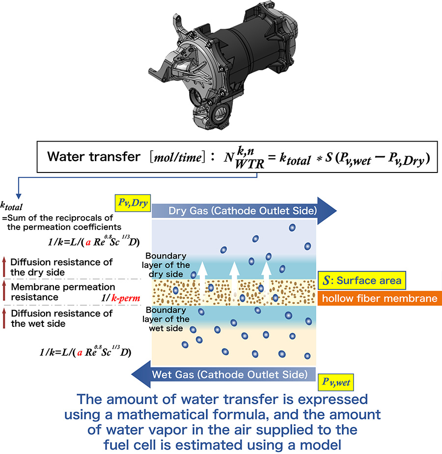
The new system estimates the amount of water vapor in the ambient air supplied to the fuel cell using a model-based estimation method and realizes optimal humidity control based on that model using an electric temperature control valve and a high-efficiency humidifier. This technology enables more precise control – lowering the stack temperature to increase the humidity and increasing the temperature to lower the humidity. Such precise control of humidity and temperature enables the system to stabilize the stack's power generation and contributes to a further increase in durability by preventing the deterioration of the cell by increasing the amount of humidification compared to the previous system.
Electric temperature control valve
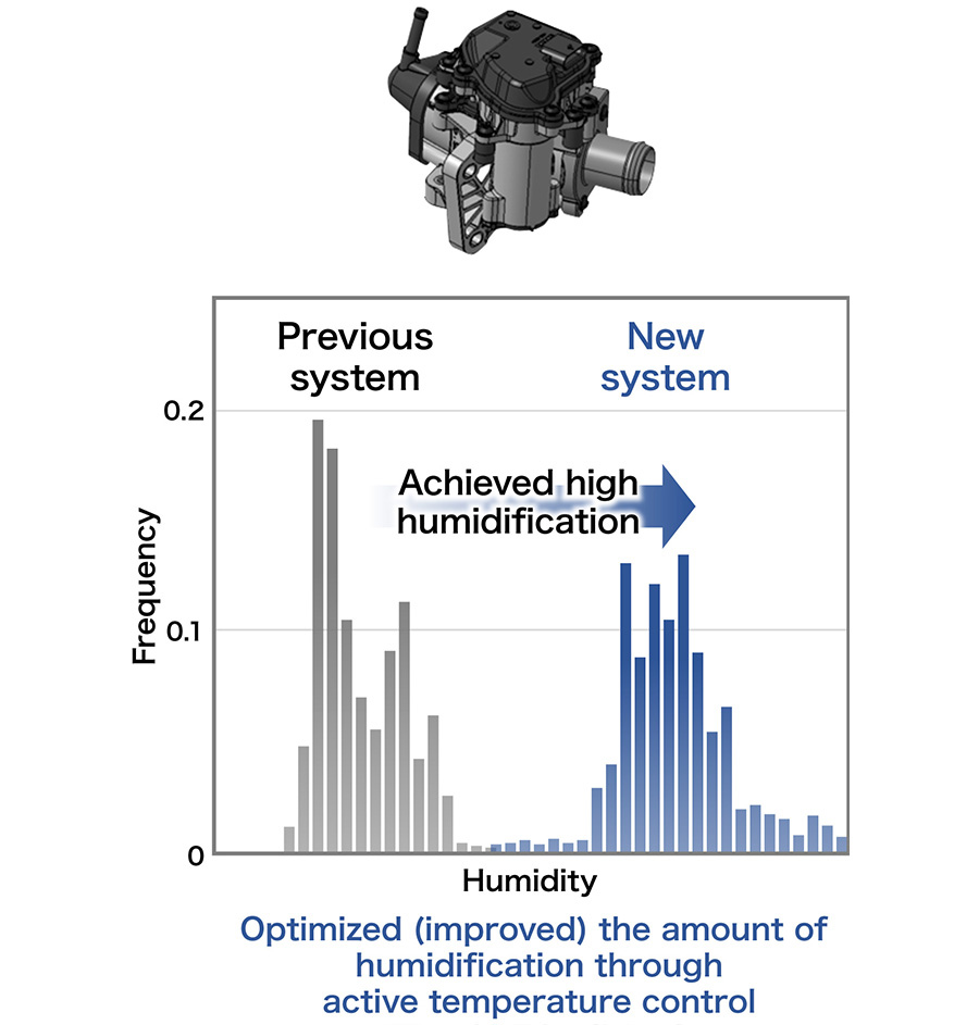
High-efficiency humidifier
When starting up in a low-temperature environment, the system increases the amount of heat generated by performing power generation operation while reducing the amount of air supplied in the hydrogen-air ratio. Rapid warm-up is performed until stable power generation is possible. This resulted in a 90% reduction in startup time at -20°C (-4ºF) compared to the previous system, as well as a significant reduction at -30°C (-22ºF).
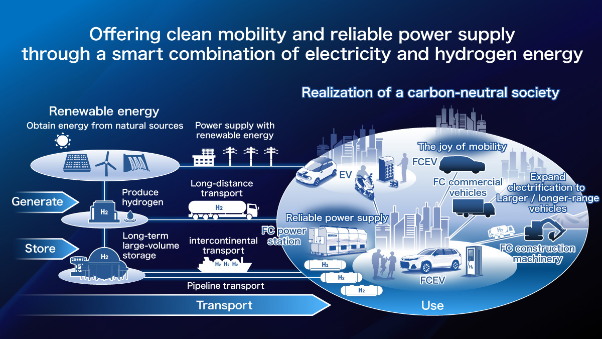
Realizing a carbon-neutral society through the versatile use of fuel cells
Honda's goal is to expand the “use” of hydrogen by making its fuel cell system available for a variety of applications.
By working toward the establishment of a clean “hydrogen circulation cycle” which consists of elements of “generate,” “store,” “transport” and “use,” and also by building the “hydrogen ecosystems” that include hydrogen supply, Honda will continue contributing to the realization of an environmentally-responsible future with utilization of hydrogen, which will lead to the realization of a carbon-neutral society.